Facebook
 Google
 GitHub
 Linkedin
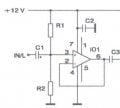
I have a schematic of an Op being used as a buffer, I think. It is powered by twelve volts and seems to be biased by a voltage divider.
the non-inverting input receives the audio signal from a phone through an audio jack.
I would assume one could leave out the resistor R1 and R2 and just connect pin 6 to pin 2 to configure it as a 1AV (gain) op amp as well as the two rails.
so my question is:
what are the resistors being used for and what formulas are relevant if this is a biasing method.
feedback would help me greatly.