Exact? No, it is a RC controlled circuit, the component variation with temperature and humidity is too great. You can get very close however. If you look at the datasheet on 555's it will give you the common formula's, some of them are quite accurate.
As I mentioned in another post, I am doing a digital clock using LEDs , using 555 and 4017. I made it to count 10 Seconds in 4017 which is drived by 555 clock. I want to convert these seconds to Minutes. I have an option that i can increase the number of 4017 ICs to increase the Seconds count then i can drive the Minutes 4017. but I want to show the minutes(12LEDs X 5 mins) and Hours (12LEDs X 1 Hr) . Is it possible to achieve these only by using 555 and 4017 ICs. I am ready to increase the Number of 4017 ICs. only thing is I dont want to show the seconds in LED. Just I want to show minutes and hours.
You can do this, but remember that your accuracy will be very poor. A better circuit IMO is the 4060 using a 32,768 crystal. Even before you tweak it it will be more accurate than a 555 could ever hope to be.
A suggestion, don't start new threads for a project, use the old one instead. You keep a continuity of thought going that way.
If you have a 12 step counter just feed the largest digit into the next 12 counter, it will do what you want. Schematics are always your friend though, draw it up!
I accept both, "don't start new threads for a project, use the old one instead. You keep a continuity of thought going that way."
"Schematics are always your friend though". Still I started this becoz I thought i ask only about 555 On time and OFf time. then it became to discuss everything.
anyway i try to keep it in mind....
And,
"A better circuit IMO is the 4060 using a 32,768 crystal."
Is it easy to do this? Because I have No knowlegde about crystals and I have never seen also. thats wat i thought of doing using 555. If I plan for the method you suggested where from I start? wat type and value of crystal should i buy? more details regarding this will help me lot. 4060 with crystel is to genrerate the clock pulses?
Well, "exact" has various meanings. One could argue that nothing involving time can be exact.
However, this circuit that I copied from Audioguru and which is also in your first link provides very close to 50% duty cycle.
Frequency will vary with temperature for the reasons mentioned; however, duty cycle should be pretty close to 50% as charge and discharge are through exactly the same timing components.
Well, "exact" has various meanings. One could argue that nothing involving time can be exact.
However, this circuit that I copied from Audioguru and which is also in your first link provides very close to 50% duty cycle.
Frequency will vary with temperature for the reasons mentioned; however, duty cycle should be pretty close to 50% as charge and discharge are through exactly the same timing components.
This works well with a CMOS 555, because the output swings rail to rail. The bipolar 555's high level is about 1.4 volts shy of the rail, so the duty cycle will be noticeably greater than 50%.
This works well with a CMOS 555, because the output swings rail to rail. The bipolar 555's high level is about 1.4 volts shy of the rail, so the duty cycle will be noticeably greater than 50%.
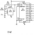
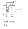
HI, Thanks for all your suggestions, I have come up with a diagram. Counting Seconds using 555 and 4017. I am trying to set the Seconds in 4017. I am adjusting the VArialble resistor in 555 to match the 4017 output to Clock seconds. Is there a perpect resistor values which directly give the second Seconds OP in 4017. Plz give suggestion , i bought several 4017s to acheive this. My first thing is I need to adjust the First 4017 to count for Seconds exactly.
I have attached 2 diagrams Fig 1 and Fig 2. please suggest me the right way and right values to achieve this. Thanks...
If you are trying for a 1 second pulse, you would be much better off running a divide by 32768 (2^15) IC.
Electronic components tend to be more stable in the kHz to Mhz range. Tolerances of 5% on a nanosecond are a lot tighter than 1% tolerance on a 1mS timer.
For a 1 second pulse, these are the most accurate:
1) Cesium fountain laser frequency source at NIST
2) HP 5060A Cesium Beam Clock Source
3) WWVB 1 second pulse with propagation delay accounted for.
4) 60Hz (US) Line Frequency Source
5) Temperature controlled precision cut quartz crystal (OXCO)
6) Crystal Oscillator divided down
..
..
..
10) R/C Delay Circuit (far less accurate than any methods above)
If you use a 555 as a reference for your clock, it will probably be off by at least several minutes per day, no matter how closely you try to adjust it. As others have said, you would be much better off to use a CD4060 and a 32768Hz crystal.
If you are just trying to demonstrate that you know how to build a circuit that works like a clock, but can't keep time, a 555 would be fine.
You don't need a 50% duty cycle clock pulse. What is the meaning of the title of this thread?
to the OP, you may find this site very useful, you can ignore the nixie portion, but it explains everything you need about the logic, save maybe driving a 7 segment.
If you are trying for a 1 second pulse, you would be much better off running a divide by 32768 (2^15) IC.
Electronic components tend to be more stable in the kHz to Mhz range. Tolerances of 5% on a nanosecond are a lot tighter than 1% tolerance on a 1mS timer.
For a 1 second pulse, these are the most accurate:
1) Cesium fountain laser frequency source at NIST
2) HP 5060A Cesium Beam Clock Source
3) WWVB 1 second pulse with propagation delay accounted for.
4) 60Hz (US) Line Frequency Source
5) Temperature controlled precision cut quartz crystal (OXCO)
6) Crystal Oscillator divided down
..
..
..
10) R/C Delay Circuit (far less accurate than any methods above)
Depends on which country you are in. In the US, mains are extremely well regulated and adjusted for any prior timing errors. In other countries, a crystal oscillator would be more accurate than the mains frequency.
Depends on which country you are in. In the US, mains are extremely well regulated and adjusted for any prior timing errors. In other countries, a crystal oscillator would be more accurate than the mains frequency.
so if you had a 4017 with an antenna on the input pin you could derive the frequency that way?
i know theres enough 60Hz going on to trigger it if its on a breadboard. http://forum.allaboutcircuits.com/showthread.php?t=47400
so if you had a 4017 with an antenna on the input pin you could derive the frequency that way?
i know theres enough 60Hz going on to trigger it if its on a breadboard. http://forum.allaboutcircuits.com/showthread.php?t=47400
finally i came up with a oscillator using crystal. its producing 1Hz pulze. I am feeding this to 4017ICs to count seconds, mins and Hours. everything is done. Now I can put some LEDs for Mins and Hours to show the time. But I am thinking of using 7-Segment display. i have some displays.. i want to connect this 7-S display to the 4017 IC. is there any suitable IC that i can use to convert the clock pulzes from 4017 and give OPs to feed 7-Segment display?
finally i came up with a oscillator using crystal. its producing 1Hz pulze. I am feeding this to 4017ICs to count seconds, mins and Hours. everything is done. Now I can put some LEDs for Mins and Hours to show the time. But I am thinking of using 7-Segment display. i have some displays.. i want to connect this 7-S display to the 4017 IC. is there any suitable IC that i can use to convert the clock pulzes from 4017 and give OPs to feed 7-Segment display?
Please post a schematic. If you have what I think you have, decoding from your counter outputs to 7-segment decoder/drivers would be a nightmare of small-scale logic ICs.
You need to use BCD counters, not Johnson counters (which is what 4017s are). BCD counters interface directly to 74xx47 decoder/drivers.

 Facebook
 Google
 GitHub
 Linkedin