On/Off Indicator using a Current Transformer

inwo

Joined Nov 7, 2013
2,419
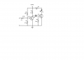
The first wall wart volunteer was not separately wound. :(

It was bifilar wound with wax though, so it gave up a few secondary turns easily.

Got to get to the gym now, but a few turns thru the core gave me 10 volts out. Measured with a low impedance analog meter and 100 watt incandescent load.

I'll figure out the rest when I come back.
 

inwo

Joined Nov 7, 2013
2,419
I'll be a few minutes late. :)
Connected an led. No other components.

Lights about 1/2 with the 100 watt bulb load.
 

inwo

Joined Nov 7, 2013
2,419
10 turns which should be feasible up to 15 or 20 amps even.

1 amp thru the 10 turns gives 4ma thru led.

120vac primary left intact for led.

A 240 volt transformer might be better for less than 1 amp loads.
This one should be scalable for 15 or 20 amp loads.

Slight forward current gain with an inverse parallel diode.
I kind of like the one component design.

Inrush of incandescent gives quite an output pulse, but heater load shouldn't stress anything.

Could check peak inverse on the scope. Transformer is so loosely coupled that the current should be safe in zener.

Is that right?
Don't know what the term is for an led.
 

Attachments

KMoffett

Joined Dec 19, 2007
2,918
This is the current-sense part of a remote dust collector switch I made for a table saw. I just replaced my relay with an LED and resistor. Smaller wire and more wraps will increase the sensitivity if needed. The transformer was a couple bucks from AXMAN Surplus in St Paul. So the hardware cost for a bunch of indicators shouldn't be too much.

Ken
 

Attachments

inwo

Joined Nov 7, 2013
2,419
Or if you have to use a low output ct below .6 volts output. You will have to amplify signal first.
Something like this should work. No filtering shown. May not need any.by keeping impedance low.
 

Attachments

wayneh

Joined Sep 9, 2010
17,498
I just tried winding a hundred turns of #30 wire around an 8 gauge wire with 3 amps of 60 Hz. running through it. Couldn't detect any voltage at all ...
Hmmm, that's odd. Wouldn't you expect more emf from 300 amp-turns? I'm too rusty to make the calculations but just by gut it seems like 300A•T should give a good response.
 

inwo

Joined Nov 7, 2013
2,419
Hmmm, that's odd. Wouldn't you expect more emf from 300 amp-turns? I'm too rusty to make the calculations but just by gut it seems like 300A•T should give a good response.
Must be about coupling.
Magnetics are my weak spot.

If the #8 @ 3amps went thru a suitable core. And the 100 turns were wound on the core?
 

MaxHeadRoom

Joined Jul 18, 2013
28,690
I haven't seen anything on the dangers of using a CT yet regarding the possible very high voltage?
If using a commercial type, these are low turn primary to high secondary, the current is inversely proportional, so the secondary current is a lot less than the primary, but the voltage is directly proportional as in any transformer, this can produce very high or dangerous voltages if left open circuit.
This is why when not in use, a CT should always have a shorted secondary and when in use have a low resistance shunt of some kind, moving coil meter, relay etc.
Max.
 

#12

Joined Nov 30, 2010
18,224
Hmmm, that's odd. Wouldn't you expect more emf from 300 amp-turns? I'm too rusty to make the calculations but just by gut it seems like 300A•T should give a good response.
No core, just wound the turns on the insulation of the 8 ga. wire. My bad? Should have used a small toroid core?

(Magnetics is a bad area for me, too.)
 

wayneh

Joined Sep 9, 2010
17,498
My bad. The magnetic field induced by current in the #8 wire would be circular around the wire, just like the wrap-around. So the magnetic field lines are not cutting through the center of the little wire "solenoid". So no emf. Gawd this stuff has always confused me.
 

MaxHeadRoom

Joined Jul 18, 2013
28,690
http://www.electronics-tutorials.ws/transformer/current-transformer.html

Another quote:

Unless a burden (i.e. meters, relays, etc.) is connected to the CT, current transformers should always be shorted across the secondary terminals. The reason is very high voltages will be induced at the terminals. Think of the CT as a transformer, with a 1 turn primary and many turns on the secondary. When current is flowing through the primary, the resulting voltage induced in the secondary can be quite high, on the order of kilovolts. When a CT fails under open circuit conditions, the cause of failure is insulation breakdown, either at the shorting terminal strip, or at the feedthrough (in the case of oil filled apparatus), because the distances between terminals are not sufficient for the voltages present.

Max.
 

inwo

Joined Nov 7, 2013
2,419
Very true at high current levels.
With the transformers we're using at the low current and coupling, hard to get enough voltage to forward bias a diode.

Theoretically, I suppose we could reach levels, open circuit, to damage sensitive devices or arc over.

I could add a meg-ohm or so across the transformer.

Good catch.
 

inwo

Joined Nov 7, 2013
2,419
ps.

Even though I commented on, and knew about the precautions from electrician training, I never understood the theory.

Ratios are only like 200/5 and such.
Input voltage is only going to be the voltage drop from impedance going thru the ct. (seems to me)
A few volts at most. X 40 or 100 maybe?
Haven't looked for the math. Could be it's more than I suspect. :confused:
 

oagudia

Joined Mar 25, 2014
2
Im using this sensor, and im reading always a few mV values.
I have always wrong measures?
There are other good sensors better than ASM-010

Good Luck!
 

oagudia

Joined Mar 25, 2014
2
I'm fighting with ASM-010 sensor, so i'm trying to make some code to measure the current through this sensor and Im getting some problems.

The problem I have is that i dont know how to read an AC value with my arduino. I have tried to sample Volts signal but I failed.

I have read a lot from this web:

http://openenergymonitor.org/emon/buildingblocks/ct-sensors-interface

and I know im close to achieve my aim. Is there anybody who has made some code for arduino or something to control this sensor?

Thanks a lot
 

KMoffett

Joined Dec 19, 2007
2,918
I don't work with Arduino but I suspect that it would be better to amplify the CT's output with an opamp, run it through a precision rectifier opamp, and filter the pulsating DC output with a capacitor. Then read the DC voltage into the Arduino's ADC.

Ken
 

AnalogKid

Joined Aug 1, 2013
11,051
In post #24, KMoffett has a circuit that partly answers the original question. Attached is a schematic with both a comparator version and a different approach to the single-transistor circuit, using a coupling capacitor to level-shift the signal for better transistor drive. In all cases you have some form of level detection followed by a missing-pulse detector and LED driver.

The AC1005 datasheet is pretty clear about 1 amp of primary current producing 1 volt rms into 1 K. If that is confirmed, then another option is to replace the single transistor with 1/7 of a ULN2003 darlington transistor array. Eliminates a few connections and packages. I might model that tomorrow and see how it looks.

ak
 

Attachments

Top