 Facebook
 Google
 GitHub
 Linkedin
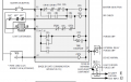
Dose the following circuit provide an on delay for CR5, or off delay, or both?
I'm trying to figure out the purpose of the time constant RC.
The resistor is 15k and the cap. is 47ufd.
Coil resistance is 1k.
Thanks
I'm trying to figure out the purpose of the time constant RC.
The resistor is 15k and the cap. is 47ufd.
Coil resistance is 1k.
Thanks
Attachments
-
 96.6 KB Views: 43


