Old guy needs help for a simple project = LED to show motor run direction

B-JoJo-S

Joined Jan 3, 2026
385
Also - D1 might not be necessary since the switch either shorts negative to negative and the relay will not activate. Or when the switch is flipped the relay is now powered positive to negative, current flows and the relay activates. So I think you can ignore the diode. It's not necessary.
 

ElectricSpidey

Joined Dec 2, 2017
3,340
You don't need any fans or extra relays and power supplies.

But I would suggest buying a new Bi-Color LED, those old Radio Shack LEDs are not very bright, and you can drive them with a lot less current and still be much brighter.
 

Thread Starter

cazksboy

Joined Nov 9, 2009
63
You don't need any fans or extra relays and power supplies.

But I would suggest buying a new Bi-Color LED, those old Radio Shack LEDs are not very bright, and you can drive them with a lot less current and still be much brighter.
Thank you for that....hmm, I was wondering about that... all this talk about being doubtful about the brightness of my 15-year old bicolor LED was concerning to me. Time for another purchase from DigiKey.
 

dl324

Joined Mar 30, 2015
18,403
all this talk about being doubtful about the brightness of my 15-year old bicolor LED was concerning to me.
The LED you're using was designed much before 2010. Modern LEDs have brightnesses orders of magnitude greater.
I can read (and understand) a SIMPLE schematic like what you posted here.
That was more of a wiring diagram than an actual schematic. Well drawn schematics don't have to resort to using meaningless colors.
 

B-JoJo-S

Joined Jan 3, 2026
385
Well drawn schematics don't have to resort to using meaningless colors.
Well-drawn schematics are like the secret language of experienced electronic hobbyists, techies, and engineers. Colors can really help beginners get a better grasp of what’s happening. When I was just starting out, following a schematic wasn’t always the easiest. So, I’d sit with a schematic and use a highlighter to highlight the circuits, which helped me understand them better.

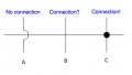
As for what makes a schematic well-drawn, it’s a bit of a matter of opinion. For example, using a jump-over line to show a line that skips over another line it crosses has been a common practice for ages. Lines that intersected were usually thought to be connections. That’s how I learned it initially. Now, lines might cross, but they don’t connect unless there’s a dot at the intersection, indicating that the points are connected.

Examples:

Screenshot 2026-01-17 at 10.19.26 AM.png
In the past, the middle example might have been thought of as a connection. What do you think is better? I usually use the third one to show a connection, while the second one doesn’t really mean that. But we often work with old drawings and schematics, and without knowing which method was used, it’s easy to get mixed up. I don’t think there’s really a “Well Drawn Schematic” without making everything clear.

In drafting, we use a table to show different characters, like the ones above. Even though I’ve mostly worked in manufacturing, I’m not new to electronics. I have my own preference, but does someone new to electronics have the same understanding as we do?
 

B-JoJo-S

Joined Jan 3, 2026
385
Not to beat this horse to death:
Screenshot 2026-01-17 at 10.39.59 AM.png
Here's an example outside of what I drew. Notice that a the horizontal line makes a connection indicated by a dot but the line breaks where it crosses another line. (source: https://forum.allaboutcircuits.com/threads/industrial-compressor-circuit-diagram-help.209386/)

Screenshot 2026-01-17 at 10.40.39 AM.png
Here's a slightly different drawing where lines cross without the dot which, since lines with dots indicate a connection; the intersection without a dot suggests no connection.
Screenshot 2026-01-17 at 10.43.38 AM.png
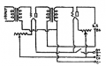
This one is from an old tube amplifier circuit. Notice lines that cross over each other have the half circle indicating no connection. To be sure, there are numerous conventions out there.

OK, off this horse now.
 

dl324

Joined Mar 30, 2015
18,403
Colors can really help beginners get a better grasp of what’s happening. When I was just starting out, following a schematic wasn’t always the easiest.
Even when I was in college, I didn't use colors on schematics.

My first job out of school was assembling and troubleshooting computers (HP 3000 Series III) that were about the size of a refrigerator based on TTL logic (except for main memory). It consisted of about a dozen different boards and 3 power supplies. The complete set of schematics was 2-3 dozen E-sized (34" x 44") schematics. They were monochromatic (blue line).
So, I’d sit with a schematic and use a highlighter to highlight the circuits, which helped me understand them better.
I use a highlighter when I'm prototyping a circuit to help me keep track of the portions that have been completed. I used highlighters on a few schematics when I was trying to analyze them. But it was more to separate wires that ran parallel for longish distances.
As for what makes a schematic well-drawn, it’s a bit of a matter of opinion. For example, using a jump-over line to show a line that skips over another line it crosses has been a common practice for ages.
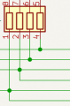
The time when the schematics were created often determines whether "humps" and "dots" were used. If humps are being used, then connection dots aren't. If connection dots are used, then humps aren't. I only take exception when humps and dots are used together. That just seems silly to me.
I have my own preference, but does someone new to electronics have the same understanding as we do?
The OP's original circuit was black and white, so he seems to be beyond the need to use colors as a crutch.
 

B-JoJo-S

Joined Jan 3, 2026
385
f humps are being used, then connection dots aren't. If connection dots are used, then humps aren't. I only take exception when humps and dots are used together. That just seems silly to me.
Silly? Yes. But some novices - not people who went to college to study this stuff, which I didn't, some people mix techniques without realizing it. And I agree, dots and the absence of humps are usually a pretty good indicator.
The OP's original circuit was black and white, so he seems to be beyond the need to use colors as a crutch.
True. But the TS also said (TS stands for Thread Starter and OP stands for Original Poster) they are new to this stuff {edit} have been away for a while {end edit} and needed help figuring out the goings on of his proposed circuit.

For some reason I'm unable to open the pictures provided by the TS. Perhaps it's on my end, but.
 
Last edited:

B-JoJo-S

Joined Jan 3, 2026
385
OK, was able to open it with Chrome.

Screenshot 2026-01-17 at 10.58.57 AM.png
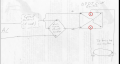
Here, the TS uses two humps. One adjacent the BR and one on the DPDT switch.

Question for the TS: Is the DPDS switch one with a Center Off position?
 

dl324

Joined Mar 30, 2015
18,403
But the TS also said (TS stands for Thread Starter and OP stands for Original Poster) they are new to this stuff and needed help figuring out the goings on of his proposed circuit.
He said that he dabbled in high school and is now old and doesn't trust himself.
I used to dabble in electronics in high school, but now I'm old and I don't trust my memory or my judgement for even a simple project.
So that's why I'm here asking for help.
For some reason I'm unable to open the pictures provided by the TS. Perhaps it's on my end, but.
Duplicate problem in the original post and a moderator messed up while trying to clean them up. They were reposted in #12.
 

MrChips

Joined Oct 2, 2009
34,948
Well-drawn schematics are like the secret language of experienced electronic hobbyists, techies, and engineers. Colors can really help beginners get a better grasp of what’s happening. When I was just starting out, following a schematic wasn’t always the easiest. So, I’d sit with a schematic and use a highlighter to highlight the circuits, which helped me understand them better.

As for what makes a schematic well-drawn, it’s a bit of a matter of opinion. For example, using a jump-over line to show a line that skips over another line it crosses has been a common practice for ages. Lines that intersected were usually thought to be connections. That’s how I learned it initially. Now, lines might cross, but they don’t connect unless there’s a dot at the intersection, indicating that the points are connected.

Examples:

View attachment 362244
In the past, the middle example might have been thought of as a connection. What do you think is better? I usually use the third one to show a connection, while the second one doesn’t really mean that. But we often work with old drawings and schematics, and without knowing which method was used, it’s easy to get mixed up. I don’t think there’s really a “Well Drawn Schematic” without making everything clear.

In drafting, we use a table to show different characters, like the ones above. Even though I’ve mostly worked in manufacturing, I’m not new to electronics. I have my own preference, but does someone new to electronics have the same understanding as we do?
drawing connections.jpg

If your drawing has A or C, then B means "No connection".
If your drawing does not have A nor C, then B means "Connection".

Edit: A is now obsolete. Use B and C only to show unconnected and connected junctions. To be strict and consistent, T-junctions must show a dot.
 

B-JoJo-S

Joined Jan 3, 2026
385
View attachment 362249

If your drawing has A or C, then B means "No connection".
IF your drawing does not have A nor C, then B means "Connection".
Thanks. Didn't know that before.
Without qualification, DPDT would be 2 positions. He made a C-off notation on the schematic, so it has 3 positions.
Upon reviewing this thread I found a picture showing a center off switch.

Granted, there are a lot of things I don't know myself. Gaining more knowledge is the #1 reason why I came here looking for information. My first thread was about car battery voltages. I know a standard alternator puts out X volts but didn't know what Y volts measured on a resting battery meant. So I'm learning as I go.

Not to get off topic.
 

Thread Starter

cazksboy

Joined Nov 9, 2009
63
OK, was able to open it with Chrome.

View attachment 362248
Here, the TS uses two humps. One adjacent the BR and one on the DPDT switch.

Question for the TS: Is the DPDS switch one with a Center Off position?
Yep, the switch has a Center off position. I bought it from Radio Shack the same day I bought the now-outdated LED. I use it all the time. Hopefully this pic will be visible - my homebuilt box as it sits currently. You can see the switch with its center-off position.
DSCF7222.JPG
 
Last edited:

AnalogKid

Joined Aug 1, 2013
12,174
If your drawing has A or C, then B means "No connection".
IF your drawing does not have A nor C, then B means "Connection".
A solution (THE solution?) is D:

D.1 - Never have a crossed connection. Un-dotted crossed lines never connect.
D.2 - Break up C into two T connections next to each other.
D.3 - Use a connection dot with each T.

This is not only completely unambiguous, but also much easier to edit / modify / whatever.

I'm not up on all of the latest CAD packages. Is there a schematic package that allows un-dotted + or T connections?

ak


View attachment 362249
 

Thread Starter

cazksboy

Joined Nov 9, 2009
63
Thanks guys, you've all been a big help and informative.
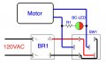
I've decided to go with the last diagram from B-JoJo-S:
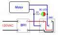
01-17-2026_Diagram Adding LED To Motor_by B-JoJo-S.jpg
I've got a 33k-ohm 1 watt resistor on its way to me from DigiKey.
As soon as it gets here I'm going to put this thing together. I decided to just use the outdated LED I already had in hand, because I'm sure it will be bright enough to see with the room lighting in my workshop - and besides, I can tell which way my lathe motor is running just by looking at it...it's only going to be there as window dressing.
One final question: where would you guy go to buy one or two bi-color LEDs? The pickings seem pretty slim in my short list of supplier bookmarks - even Mouser doesn't have a decent bi-color LED with green/red as the colors.
Thanks again.
 

B-JoJo-S

Joined Jan 3, 2026
385
I would like to declare that this diagram comes from others who essentially said the same thing LONG before I did. My approach was to use an external power source but that was when I was thinking you had two distinct LED's. My idea had no support so I basically drew what others were saying. The drawing is not my design.
 
Top