Old Craftsman AC motor circuit problem

Thread Starter

Shwermy

Joined Apr 4, 2022
8
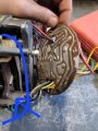
Heya! I've been struggling with this old craftsman variable speed motor. I've torn it completely apart and put it back together and determined it has to be something in the circuit board not letting it start. The armature spins freely maybe a little drag. When I turn the switch it will rotate half a turn the flip the overload protection. I cant see any burn marks or other damage to the board. I'm kind of lost at this point expecially as this motor is before my time. I am pretty new at circuits I'm a mechanic by trade not a electrician :p. Any help would be greatly appreciated! If more pictures needed i can post. Thanks in aadvance!! If post not allowed i appologize.16490843996881284518019958760176.jpg
1649084450326666390916823220394.jpg16490844819918419282279118902226.jpg16490844993536576962989641471428.jpgmotor model: 266.23480. 60 cycle, 1 phase. 115 volt, 1/2hp, 500-5000rpm
 

LowQCab

Joined Nov 6, 2012
4,072
Unless You can "reverse-engineer" a Schematic,
it's a crap-shoot trying to replace the 2 SCRs, ( the devices with 2-pins ).
If the other 3 devices, ( Diodes ), are de-soldered and taken out of Circuit, they can be tested,
and their polarities verified,
and could be readily replaced with generic parts.

But do You really want to abuse yourself that much to keep it all original "looking" ?

Most likely, You have a standard "Universal-Motor",
which will run on AC or DC at standard Mains-Voltage.

There are plenty of aftermarket speed-control-modules,
or separate external speed-controls in their own box,
that are widely available, and reasonably priced.
If You need speed-control ability, a new external controller is what I would recommend,
then the only other thing You will need is a new Power-Cord connected to the Red & Black wires,
( and, of course, a Grounding-Wire to the Case of the Motor-Housing ).
.
.
.
 

Thread Starter

Shwermy

Joined Apr 4, 2022
8
Unless You can "reverse-engineer" a Schematic,
it's a crap-shoot trying to replace the 2 SCRs, ( the devices with 2-pins ).
If the other 3 devices, ( Diodes ), are de-soldered and taken out of Circuit, they can be tested,
and their polarities verified,
and could be readily replaced with generic parts.

But do You really want to abuse yourself that much to keep it all original "looking" ?

Most likely, You have a standard "Universal-Motor",
which will run on AC or DC at standard Mains-Voltage.

There are plenty of aftermarket speed-control-modules,
or separate external speed-controls in their own box,
that are widely available, and reasonably priced.
If You need speed-control ability, a new external controller is what I would recommend,
then the only other thing You will need is a new Power-Cord connected to the Red & Black wires,
( and, of course, a Grounding-Wire to the Case of the Motor-Housing ).
.
.
.
I appreciate your reply. I have 0 care about it being original or not. This motor is for my drill press, I really would like it to be variable speed as well so I don't have to change the belts non stop and I have a wider range of speeds. Let me see if I'm following you, I should be able to just remove that circuit board and directly wire up to the motor(the bursh/armature area) and use a external speed controller to retain my variable speed functionality. And the black and red wires you're mentioning would be the ones coming from the brush area? Lastly if you could point me in the direction of finding a external speed controller that would be much appreciated. This is all very new to me and I'm happy to learn about it. Thank you for being patient with me. :)
 

LowQCab

Joined Nov 6, 2012
4,072
A "Universal-AC-DC-Motor" may be a poor choice for a Drill-Press.
These types of Motors may not have a stable, fixed RPM that can be relied upon.
This may vary with different Motor-Designs, and Wiring-Schemes.
There are no guarantees as to the particular Torque and RPM characteristics that this Motor may have,
and they are very likely NOT going to be stable.

For a Drill-Press, I seriously suggest that You go with a generic "Capacitor-Start-Synchronous-Motor".
~1/3 to ~1/2-Horsepower should be completely adequate for virtually all hobbyist uses,
and will provide very stable and predictable operation,
along with a multi-groove Pulley-System for regulating speed.
There are very good reasons why it's been done this way for over ~100-years.
.
.
.
 

Thread Starter

Shwermy

Joined Apr 4, 2022
8
A "Universal-AC-DC-Motor" may be a poor choice for a Drill-Press.
These types of Motors may not have a stable, fixed RPM that can be relied upon.
This may vary with different Motor-Designs, and Wiring-Schemes.
There are no guarantees as to the particular Torque and RPM characteristics that this Motor may have,
and they are very likely NOT going to be stable.

For a Drill-Press, I seriously suggest that You go with a generic "Capacitor-Start-Synchronous-Motor".
~1/3 to ~1/2-Horsepower should be completely adequate for virtually all hobbyist uses,
and will provide very stable and predictable operation,
along with a multi-groove Pulley-System for regulating speed.
There are very good reasons why it's been done this way for over ~100-years.
.
.
.
I appreciate the input and I will look into the capacitor start motor. This was just the motor that was on the drill press when I go it, it's a 1955 floor standing craftsman drill press. Plus it has a very funky mounting system for the motor, but i can fabricate something. The only forum I found on this motor talked about them being used on those and lathes, it was from the sears catalog. Thank you again for all your help!
 

MaxHeadRoom

Joined Jul 18, 2013
28,686
If you want a variable speed motor for a drill press, many have used the 2hp- 3.5hp DC Treadmill motors and controllers, such as the MC-60 or the better MC-2100 PWM versions.
 

LowQCab

Joined Nov 6, 2012
4,072
I would hazard a guess that some brilliant marketing guy though this Universal-Motor was the answer to
under-cutting the competition's price when Hobbyist-Power-Tools were
in their hay-day, and any Dad worth his salt had a garage full of Power-Tools.
And, this also sounds like some of the current, super-cheap, portable Table-Saws from Harbor-Freight,
which would lasts about ~2-days on an actual Job-Site.
( at least they're light-weight )
.
.
.
 

bassbindevil

Joined Jan 23, 2014
828
I've come across several drill presses fitted with washing machine motors which include a two-speed gearbox. But it would be cool to keep the original variable speed motor. I'd check the SCRs and diodes for shorts. Examine the board carefully for cracked traces or cold solder joints. On the other other hand, you could just wipe it down and put it up on a high shelf with other neat old stuff to collect dust.
 

Thread Starter

Shwermy

Joined Apr 4, 2022
8
I've come across several drill presses fitted with washing machine motors which include a two-speed gearbox. But it would be cool to keep the original variable speed motor. I'd check the SCRs and diodes for shorts. Examine the board carefully for cracked traces or cold solder joints. On the other other hand, you could just wipe it down and put it up on a high shelf with other neat old stuff to collect dust.
That's pretty crazy for the two speed washing machine gearbox, I approve haha. The scrs I got continuity and a ohm reading of .34 on both. The diodes I ran into the problem of I cant find them anywhere online to figure anything out since I don't fully know what I'd be looking at.
 

MaxHeadRoom

Joined Jul 18, 2013
28,686
By all appearances, that is a SCR bridge with reverse protection diode.
3 rectifiers and two SCR's as is typical.
In place of the compression mount, you can get stud mount quite easily as a replacement if necessary .
The run-of-the mill Universal motor controllers are mainly a simple Triac circuit, these operate the motor with AC rather than this version which is DC .
Either will run the motor.
 

Thread Starter

Shwermy

Joined Apr 4, 2022
8
I also totally never mentioned this one of the other cool things about this motor is there is a manual switch that let's the motor spin in reverse as well.
 

MaxHeadRoom

Joined Jul 18, 2013
28,686
Is this done mechanically or electrically?
If electrical it would have to switch the polarity of either the fields or the commutator.
 

Thread Starter

Shwermy

Joined Apr 4, 2022
8
Is this done mechanically or electrically?
If electrical it would have to switch the polarity of either the fields or the commutator.
In the second photo under the circuit board you will see a brown disc with a nub that's what you rotate to the right or left for direction and the center is netrual
 
Top