Offset adjust for AWM720P1 flow sensor.?

Thread Starter

andriasm

Joined Aug 2, 2022
25
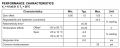
I have a flow sensor -> AWM720P1 (Honeywell). And I need to zero this variation of Vout.
1660757658329.png
I need to keep the Vout in 1.00 V with no flow reading.
1660757821043.png

My problem today is that if we calibrate the equipment when the sensor has 1.00Vout (no flow), sometimes the Vout vary (even with no flow), which looks like the sensor is reading some flow into that. Whats is no truth. My microcontroller has a ADC resolution of 12 bits, so any little variation of Vout results in a big read.
Can someone suggest a circuit to do that in hardware?
 

Attachments

Last edited by a moderator:

DickCappels

Joined Aug 21, 2008
10,153
First thing to do is find out what is causing the change in offset. Temperature is one suspect. Or might it be something inside the sensor such as mechanical hysteresis?
 

Irving

Joined Jan 30, 2016
3,843
What are you powering the sensor with? A schematic would be useful.

You can never remove that offset completely due to temperature variation and circuit noise. What ADC are you using?
 

Thread Starter

andriasm

Joined Aug 2, 2022
25
What are you powering the sensor with? A schematic would be useful.

You can never remove that offset completely due to temperature variation and circuit noise. What ADC are you using?
I am using the microcontroller TMS320F2809. It has a 12 bits adc.

The sensors supply is a 10 VDC voltage reference. We can discard completly the supply.
 

Irving

Joined Jan 30, 2016
3,843
OK..
So you are calibrating out the 0.3% ratiometric variability. What size offset are you seeing?

Therefore you only have left temperature, noise and hysteresis. How are you maintaining temperature? Though that's only ±0.25v across the whole temperature range. Intrinsic noise is unlikely, unless there is external noise in the circuit.

12bit adc reading 0 - 3v is 732uV/LSB - are you scaling the sensor's 0 - 5v output to 0 - 3v or just clipping it at 3v?
 
Last edited:

Thread Starter

andriasm

Joined Aug 2, 2022
25
OK..
So you are calibrating out the 0.3% ratiometric variability. What size offset are you seeing?

Therefore you only have left temperature, noise and hysteresis. How are you maintaining temperature? Though that's only ±0.25v across the whole temperature range
note that the flow specification table shows that in 1.00Vout (0 flow SLPM), there is a variation ±0.05 V. Can I zero this ±0.05V?
For my 12 bits ADC, it's a problem. I need to remove this variation.
 

crutschow

Joined Mar 14, 2008
34,282
For my 12 bits ADC, it's a problem. I need to remove this variation.
Why can't you just subtract the offset in software?

Edit: You have a calibrate cycle that measures the offset with no air flow, and then use that value to subtract that offset from subsequent readings.
 
Last edited:

ericgibbs

Joined Jan 29, 2010
18,766
hi and,
Are you using any software value averaging routines for the individual sample ADC readings, or any hardware filtering of the sensor output.?

E
 

DickCappels

Joined Aug 21, 2008
10,153
12 bits is a lot of bits for an A-to-D that is on the chip as the rest of the controller. Some of the questions above relate to the fact that when you start getting down close to a millivolt little things cause errors in the A-to-D. Using firmware to average a lot of readings often helps because the average value of random noise is zero.

I am not familiar with the controller you mentioned. Does it have provisions to "sleep" the controller while measurements are made? If, so do you use that or something similar?
 

Thread Starter

andriasm

Joined Aug 2, 2022
25
12 bits is a lot of bits for an A-to-D that is on the chip as the rest of the controller. Some of the questions above relate to the fact that when you start getting down close to a millivolt little things cause errors in the A-to-D. Using firmware to average a lot of readings often helps because the average value of random noise is zero.

I am not familiar with the controller you mentioned. Does it have provisions to "sleep" the controller while measurements are made? If, so do you use that or something similar?
We have an average of the samples on firmware too, but the problem is that it's not a noise. It's the natural variation sensor. On its datasheet, it shows that he can vary ± 0,5V with no flow, but this variation is the problem for us. We need to treat variation. I have no idea how can I do it by firmware, so I am searching for a hardware solution if its possible.
 

ericgibbs

Joined Jan 29, 2010
18,766
hi and,
Please post a circuit showing the sensor, power supply, and it's connection to the MCU, we may be able to suggest filtering.

E
 

DickCappels

Joined Aug 21, 2008
10,153
The recommendation that @crutschow made in post #9 is a very good one if you can assure that there is no significant air flowing through the sensor during the measurement.

In post #8 @Irving asked how you calibrate your system. The answer might give us clues to how to solve the problem.

It seems that the question of calibration air mass flow has been looked into for a very long time. The patents referenced in these patents are usually prior art and may help you find a solution. Note that some patents have expired. Patents issued before 1995 had a term of 17 years, though some may be extended.
https://patents.google.com/patent/US4986243A/en
https://patents.google.com/patent/US20130131955A1/en
 

crutschow

Joined Mar 14, 2008
34,282
On its datasheet, it shows that he can vary ± 0,5V with no flow, but this variation is the problem for us. We need to treat variation. I have no idea how can I do it by firmware, so I am searching for a hardware solution if its possible.
The only way to remove that variation is to calibrate the sensor with zero airflow (as I suggested) and possibly a known airflow.
Makes no significant difference whether that's done in software, firmware, or hardware.
There's no other magical way to get rid of the variation without first measuring it.
 
Top