I have a problem that has been bugging me for some time now that is probably simple, but I don't understand. As a foreword, I don't know much about electrical engineering as it is more of a hobby than profession for me, but I have been wanting to learn more, and have been using this project as a segue into a better understanding.
Background:
I am working on an old car (1957) that had relatively low production numbers so original parts are hard to come by and expensive when you do. I am updating the mechanicals for daily use, exchanging major components for more common parts when I can. The circuits in this car are, as expected, incredibly simple. The fuel sensor is a really basic unit that is a wound variable resistor, displaying on a magnetic pole gauge, lacking even a voltage regulator for the gauge cluster! I have attached a photo of the original wiring below the thread so that it is easier to visualize. The gauge cluster is a really beautiful design that I would really like to keep functioning, if at all possible. So far I have solutions to have all the original gauges function, except the fuel gauge.
My goal with this project has been to keep the amount of "universal" or aftermarket-designed parts to an absolute minimum, using parts from more common vehicles. The logic is that they will be far easier to locate if replacement is necessary and were likely developed with more scrutiny and designed for a longer lifespan than aftermarket parts that haven't had thousands of miles of road testing and dedicated engineering. My original fuel tank is in poor condition, along with the associated sender/pickup unit, and many years overdue for replacement. I would, ideally, like to replace the original tank with one that is more common, in addition, electronic fuel injection is much more sensitive to particulates than the original carbureted fuel delivery was.
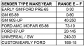
The original fuel sender was, approximately, 220 ohms when full to 20 ohms when empty, confirmed by my testing of the original sending unit with a multimeter. They only used sending units with this resistance for a three to four year period, with the earlier and later models using models that were around 73 ohms full to 10 ohms empty. Finding a tank that fits and is easily attainable is really no issue, and I have a few candidates that will work and require minimal modification. The issue lies in the resistance of the original sending unit being an odd duckling that no other manufacturer really used besides Stewart Warner, being close to the aftermarket standard of 240 full to 33 empty. Some more modern production vehicles seem to use ranges similar to the S-W fuel gauges, but none with tank sizes that will fit the chassis.
Fuel tanks that will fit seem to have associated sender ranges (of full to empty) of 73-10, 0-30, and 0-90. From the research I have done, it seems keeping the ohms moving in the same direction will be easier to adapt with no op-amp needed, and I like the fact that if a poor ground somehow results due to corrosion, the fuel level indicated will be lower than what is actually in reserve, which I prefer to an optimistic gauge. I have, as stated earlier, done some testing with the original fuel sender and a spare gauge that I have, and I have had some interesting observations that I don't really understand.
Dilemma:
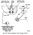
When I measure the sending unit with my digital multimeter on the 2000-ohm setting, I have confirmed that the range is (approx.) 220-210 full, to 20-10 when empty. This is with no wiring whatsoever connected, measuring directly on the sending unit itself. I took my spare gauge, sending unit, and a spare battery and made a small bench testing harness for experimentation. When all the wiring is connected (including 12v+ applied simulating ignition on), the sender and gauge works as intended, reading from slightly below E to all the way to F. What is interesting (to me anyway), and I have yet to find an answer, I am getting different resistance readings with everything but 12v positive applied. With all the wiring connected as per the diagram, I am getting exactly half the resistance readings when measuring in the same locations as the prior test, correlating to the same positions on the gauge face. I have confirmed this by measuring the resistance, disconnecting the ground leads, and watching the resistance double. What is most interesting to me, which could be pure luck, when the sending unit is manually set at the values of 10 ohms and 73 ohms, it reads slightly above F and exactly on E. I have tried to measure the resistance between SW and GA on the diagram below, but unless I am doing something incorrectly, I am not getting any measurement.
Questions/Observances:
- I am guessing that, based on above, there is some form of a resistor(s) changing the readings that I am getting, but how, where, and most importantly, why? What would be the original logic behind doing this? I have removed the fuel gauge from the cluster, and I do not see any resistors, just the magnetic windings.
- Given the data above, I am guessing it wouldn't be too much effort to essentially undo what the gauge is doing, either via a resistor or a potentiometer (I would like the potential for fine-tuning). What I don't understand is, it seems based on other research I have done, adding resistors would simply change either the low value or the high value, but this gauge is changing both values proportionally? A similar thread on here discussed the problem of introducing non-linearity when doing this, which further begs the question why this would have been done originally.
Possible Solutions (in order of preference)
- Implement some sort of circuit to use a 73-10 ohm OEM designed fuel sender and tank
- Purchase another OEM rheostat and fabricate a pickup mount and float
- Use a universal fuel sender/gauge interface module
Similar theads:
(First thread about the exact same sending unit above)
https://forum.allaboutcircuits.com/threads/adapting-a-gas-tank-sending-unit-potentiometer.125947/
https://forum.allaboutcircuits.com/threads/motorcycle-fuel-gauge-interface.128374/
https://forum.allaboutcircuits.com/...or-fuel-gauge-change-resistance-range.170732/
Background:
I am working on an old car (1957) that had relatively low production numbers so original parts are hard to come by and expensive when you do. I am updating the mechanicals for daily use, exchanging major components for more common parts when I can. The circuits in this car are, as expected, incredibly simple. The fuel sensor is a really basic unit that is a wound variable resistor, displaying on a magnetic pole gauge, lacking even a voltage regulator for the gauge cluster! I have attached a photo of the original wiring below the thread so that it is easier to visualize. The gauge cluster is a really beautiful design that I would really like to keep functioning, if at all possible. So far I have solutions to have all the original gauges function, except the fuel gauge.
My goal with this project has been to keep the amount of "universal" or aftermarket-designed parts to an absolute minimum, using parts from more common vehicles. The logic is that they will be far easier to locate if replacement is necessary and were likely developed with more scrutiny and designed for a longer lifespan than aftermarket parts that haven't had thousands of miles of road testing and dedicated engineering. My original fuel tank is in poor condition, along with the associated sender/pickup unit, and many years overdue for replacement. I would, ideally, like to replace the original tank with one that is more common, in addition, electronic fuel injection is much more sensitive to particulates than the original carbureted fuel delivery was.
The original fuel sender was, approximately, 220 ohms when full to 20 ohms when empty, confirmed by my testing of the original sending unit with a multimeter. They only used sending units with this resistance for a three to four year period, with the earlier and later models using models that were around 73 ohms full to 10 ohms empty. Finding a tank that fits and is easily attainable is really no issue, and I have a few candidates that will work and require minimal modification. The issue lies in the resistance of the original sending unit being an odd duckling that no other manufacturer really used besides Stewart Warner, being close to the aftermarket standard of 240 full to 33 empty. Some more modern production vehicles seem to use ranges similar to the S-W fuel gauges, but none with tank sizes that will fit the chassis.
Fuel tanks that will fit seem to have associated sender ranges (of full to empty) of 73-10, 0-30, and 0-90. From the research I have done, it seems keeping the ohms moving in the same direction will be easier to adapt with no op-amp needed, and I like the fact that if a poor ground somehow results due to corrosion, the fuel level indicated will be lower than what is actually in reserve, which I prefer to an optimistic gauge. I have, as stated earlier, done some testing with the original fuel sender and a spare gauge that I have, and I have had some interesting observations that I don't really understand.
Dilemma:
When I measure the sending unit with my digital multimeter on the 2000-ohm setting, I have confirmed that the range is (approx.) 220-210 full, to 20-10 when empty. This is with no wiring whatsoever connected, measuring directly on the sending unit itself. I took my spare gauge, sending unit, and a spare battery and made a small bench testing harness for experimentation. When all the wiring is connected (including 12v+ applied simulating ignition on), the sender and gauge works as intended, reading from slightly below E to all the way to F. What is interesting (to me anyway), and I have yet to find an answer, I am getting different resistance readings with everything but 12v positive applied. With all the wiring connected as per the diagram, I am getting exactly half the resistance readings when measuring in the same locations as the prior test, correlating to the same positions on the gauge face. I have confirmed this by measuring the resistance, disconnecting the ground leads, and watching the resistance double. What is most interesting to me, which could be pure luck, when the sending unit is manually set at the values of 10 ohms and 73 ohms, it reads slightly above F and exactly on E. I have tried to measure the resistance between SW and GA on the diagram below, but unless I am doing something incorrectly, I am not getting any measurement.
Questions/Observances:
- I am guessing that, based on above, there is some form of a resistor(s) changing the readings that I am getting, but how, where, and most importantly, why? What would be the original logic behind doing this? I have removed the fuel gauge from the cluster, and I do not see any resistors, just the magnetic windings.
- Given the data above, I am guessing it wouldn't be too much effort to essentially undo what the gauge is doing, either via a resistor or a potentiometer (I would like the potential for fine-tuning). What I don't understand is, it seems based on other research I have done, adding resistors would simply change either the low value or the high value, but this gauge is changing both values proportionally? A similar thread on here discussed the problem of introducing non-linearity when doing this, which further begs the question why this would have been done originally.
Possible Solutions (in order of preference)
- Implement some sort of circuit to use a 73-10 ohm OEM designed fuel sender and tank
- Purchase another OEM rheostat and fabricate a pickup mount and float
- Use a universal fuel sender/gauge interface module
Similar theads:
(First thread about the exact same sending unit above)
https://forum.allaboutcircuits.com/threads/adapting-a-gas-tank-sending-unit-potentiometer.125947/
https://forum.allaboutcircuits.com/threads/motorcycle-fuel-gauge-interface.128374/
https://forum.allaboutcircuits.com/...or-fuel-gauge-change-resistance-range.170732/
Attachments
-
 23.9 KB Views: 6