NTC Thermistor resistance value stuck

Thread Starter

Akash Joshi

Joined Jul 31, 2015
4
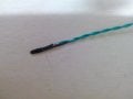
I am using NTC Thermistor bought from Mitsubishi (http://www.mmc.co.jp/adv/dev/english/contents/thermistor/lead/cn_ch.html). The sensor is made by increasing the length or the sensor wire from 30 mm to 320 mm by soldering 2 teflon wire. The sensor is then inserted into a 30 mm aluminium tube and encapsulated using sylgard 160(http://www.dowcorning.com/applications/search/products/details.aspx?prod=02356368&type=prod) silicone elastomer kit.
The wire are then heat sleeved. The sensor along with its 30 mm tube and 60 mm of its wire is then place in a water bath whose temperature varies from 10 to 4 deg c. This sensor is used to control a compressor which in-turn cools the water bath till it reaches 4 deg C

The issue is that after a fortnight or so the water bath turns into ice since the compressor does not stop. On inspecting the temperature sensor resistance it is found that it gets stuck at one particular value. After this the sensor was removed from the circuit board connection and the water bath. The sensor is kept at room temperature for a day or two and the sensor starts showing correct readings. This has happened 5 times in 3 different machines. Every time a sensor which has gone faulty shows a different reading when the resistance is stuck but always returns back to normal after a few days.

This issue has caused a lot of our machines to malfunction and we have bought 5000 such sensors. Guys please give me some suggestions and tell me if more information is required.
 
Last edited:

Alec_t

Joined Sep 17, 2013
14,313
Welcome to AAC!
Is 30mm the tube diameter or length? If diameter, then you have a very large thermal mass for such a small thermistor. Why?
The sensor is kept at room temperature for a day or two and the sensor starts showing correct readings.
A day to stabilise the reading? That suggests the thermal mass is much too high to allow proper control, or water penetration is affecting the reading.
Why heat sleeving if the sensor is to be used at near-zero Celsius?
What is the room temperature resistance of the thermistor?
Can you post a schematic showing the control circuit which includes the thermistor?
 
Last edited:

Alec_t

Joined Sep 17, 2013
14,313
Another thought. Is the water bath stirred? If not, and the sensor is near the bottom of the bath, the temperature will tend to be fairly constant at about 4C even if there is ice at the top, because of the anomalous expansion of water. See e.g. this article.
 

Thread Starter

Akash Joshi

Joined Jul 31, 2015
4
Another thought. Is the water bath stirred? If not, and the sensor is near the bottom of the bath, the temperature will tend to be fairly constant at about 4C even if there is ice at the top, because of the anomalous expansion of water. See e.g. this article.
The diameter of aluminium tube is 6 mm and length is 30 mm.

The water bath is stirred every 60 secs for 60 seconds.

The heat sleeve is used over the two teflon wires and not the aluminium tube.

Sensor reading at 25 deg C is 10 k ohms.

For example, One day when the water bath became Ice I checked the resistance of the sensor and it show 12.34 k ohms and this did not even fluctuate when the sensor was removed from the bath and squeezed by the hand. Then I kept the sensor on the table and checked the resistance to show it to my boss after 2 days and at that time it showed correct readings.

About I formation the Ice gets formed on the evaporator coils which are placed on the bottom surface and never floats.

The two silver parts are water sensors
 

Attachments

ErnieM

Joined Apr 24, 2011
8,377
From your simple experiment (something I do too as a sanity check) using your hand to change the temperature shows this thing is obviously not responding to temperature when it goes "funny."
Your methods and techniques seems very sound.

If you only have one such probe build another. Something somewhere has gone away, a connection, the NTC sensor, some other thing is just not working right and the simplest way to elimater all variables is to just make another.
 

OBW0549

Joined Mar 2, 2015
3,566
You're using Teflon insulated wire. Does Sylgard 160 bond to Teflon? If not, it's possible that water may be intruding into your sensor probe after long immersion and causing a malfunction. Then, after a few days out of water, the probe dries out and begins working correctly again. Just a possibility...
 

Thread Starter

Akash Joshi

Joined Jul 31, 2015
4
I thought of that too and yesterday I made another sensor encapsulation where the solder points are inside the 30 mm long aluminium tube and the top surface is sealed sealed with m-seal to prevent water entering the sensor probes. The testing of this sensor is going on now. I will update about the testing but I am not sure if this is the only issue(I hope it is though).
 

OBW0549

Joined Mar 2, 2015
3,566
I thought of that too and yesterday I made another sensor encapsulation where the solder points are inside the 30 mm long aluminium tube and the top surface is sealed sealed with m-seal to prevent water entering the sensor probes. The testing of this sensor is going on now. I will update about the testing but I am not sure if this is the only issue(I hope it is though).
OK, hope that solves the problem, and that it's the only issue. Good luck, and let us know how it works out!
 

John P

Joined Oct 14, 2008
2,026
I'm also thinking that water infiltration may be the issue. Teflon is used when you don't want things to stick, and maybe the silicone material isn't sealing properly to it. How about putting the sensor in a vertical tube with a sealed bottom, so you don't have to seal the wires? Or you might be able to put the sensor against the outside wall of the tank, and not concern yourself with sealing anything (except the tank, which I assume is waterproof).
 

Thread Starter

Akash Joshi

Joined Jul 31, 2015
4
Okay so conducted a experiment.

1. A sensor was made with the solder joint to extend the wires outside the aluminium tube. The joints are individually sleeved and then both of the wires are sleeved together.

2. A sensor was made with the solder joint to extend the wires inside the aluminium tube. The joints are individually sleeved and then both the wires are inside the tube hence sealed using a sealant.

3. A bare open solder joint(as seen in the image attached) was made and then tested in water.

Sensor 1 and 2 worked properly, but, to my astonishment even sensor 3 worked (obviously with a drift in resistance value measure due to the parallel resistance of water) without the resistance value getting stuck at particular value. In conclusion, I can say that water seeping might cause a drift in the resistance measured but not cause the resistance value to get stuck at one point irrespective of change in temp.
 

Attachments

Top