Facebook
 Google
 GitHub
 Linkedin
Here is a possibility:Yeah, as for me, the project that taught me the most was building a 4-bit calculator using an Alteration Quartus PLD. It could add, subtract, multiply, divide, AND, OR, XOR, etc. I could Karnaugh map the s#!% out of things... but that's digital electronics - this is analog, and I only got through Circuits II.
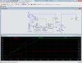
I guess I didn't post the article where I found this circuit. It lists out a lot of info:
http://www.edn.com/design/analog/4314544/Integrator-ramps-up-down-holds-output-level (article)
http://m.eet.com/media/1126960/12071-figure.pdf (actual circuit image)
I'm using the recommended LMC6484 which is rail-to-rail. The thing that gets me is that the voltage WILL ramp up linearly to max when the motor is removed, but when the motor is added, it only goes to 1.8V or so (measured from ground to base/output of the ramp circuit). It's as if I've somehow added a resistor to create a voltage divider. Shouldn't the collector and emitter be isolated from the base? Why is this impacting the circuit like this? That's why I tried randomly throwing diodes at the problem, but no joy.
Check fig 4 in the op amp data sheet. http://www.ti.com/lit/ds/symlink/lmc6484.pdf
It can only supply about 10ma at 3.7 volts.
Then if you look at fig. 5 of the transistor data sheet. http://www.onsemi.com/pub_link/Collateral/2N3055-D.PDF
You might try shorting out the resistor from the op amp to the base to see if it speeds up. If not I think it's a real problem.

We can either try to fix it or do it another way.
How much current can your 12 volt supply provide??