Not getting 18V from TC7660s charge pump. Causes?

Thread Starter

Mr. Lumbergh

Joined Jan 28, 2018
9
Pardon if this isn't in the correct forum, and please move if so.
When I'm not at my 9-5, I dabble in music, and have restored vintage amplifiers and completed several effects builds, both from scratch and from kits. So, a friend asked for my help to see why a commercial pedal of his wasn't providing increased signal gain as it is designed to. I have bit of experience with this circuit, having built a clone of the pedal that this is also a clone of (Klon Centaur for reference).
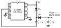
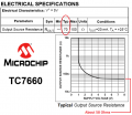
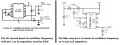
Where I'm having issues is on the TC7660s charge pump. In this circuit it's supposed to take the DC 9V in and provide 18V out on pin 8 to the op-amps, but I'm not measuring 18V at pin 8, just the same 9.37 as from the power supply. This is when I measure it from ground at the power supply plug socket to pin 8; interestingly, measuring it from pin 3 (IC ground) to 8 gives me about 0.3v.
I've swapped in different IC's from my own parts box and am having the same issue on all.
I've never bumped into this issue before on any of my own kits or scratch builds, so I'm not completely sure where I should focus my troubleshooting efforts. Any advice or pointers you may have would be greatly appreciated. Thanks.
 

BobTPH

Joined Jun 5, 2013
11,513
If you measure 9.3V from pin 8 to ground, but 0.3V from pin 8 the ground pin on the IC, the ground pin on the IC is most likely not connected to ground. Which might suggest a reason why the charge pump is not working.

Bob
 

Thread Starter

Mr. Lumbergh

Joined Jan 28, 2018
9
If you measure 9.3V from pin 8 to ground, but 0.3V from pin 8 the ground pin on the IC, the ground pin on the IC is most likely not connected to ground. Which might suggest a reason why the charge pump is not working.

Bob
I reseated the charge pump and am now getting 9.3V between pin 8 and 3 (ground). Still not getting 18V on 8 as I should.
 

smooth_jamie

Joined Jan 4, 2017
107
I reseated the charge pump and am now getting 9.3V between pin 8 and 3 (ground). Still not getting 18V on 8 as I should.
If I am reading the datasheet correctly, it needs an external cap between pin 2 and 4. The pump circuit will not work without a charging capacitor. I'd be tempted to check the external cap is OK first (which should be straight forward to check).

Alternatively, Perhaps if you can remove the IC from the socket you could test it on a breadboard? I'm not sure what equipment you have to do that though.

Additional:
Pin 5 is "Vout" for negative voltage, you should also be getting some negative voltage out of that pin between pin 5 and pin 3. What measurement do you get here?
 

Audioguru

Joined Dec 20, 2007
11,248
The 7660 produces a low output current. With V+ at 5V then the output of a voltage doubler is +8.6V with no load current or about +8V with a load current of 10mA. The capacitors must have enough capacitance to filter the output. Here is from the ICL7660 datasheet:
 

Attachments

ebeowulf17

Joined Aug 12, 2014
3,307
The 7660 produces a low output current. With V+ at 5V then the output of a voltage doubler is +8.6V with no load current or about +8V with a load current of 10mA. The capacitors must have enough capacitance to filter the output. Here is from the ICL7660 datasheet:
You're right about the output current, but I *think* you're wrong about the Vf drop. It's a different part number than what you've referenced.

I haven't built a test circuit yet, but I've picked up a few of these chips, and according to the data sheet, there's no Vf drop like in your example. I'm certainly hoping that turns out to be true. I can get away with low current for my plans, but I was counting on the full voltage range.

http://ww1.microchip.com/downloads/en/DeviceDoc/21465C.pdf

IMG_4381.PNG
 

sghioto

Joined Dec 31, 2017
8,634
The doubler circuit from post #5 works as shown. I have used that design several times.With 9 volt Vcc and 10uf caps the output is 16.6 volts .
into a 10K load. As stated 2Vcc - 2Vf = 16.6 volts with .7v diode drop.
SG
 
Last edited:

Audioguru

Joined Dec 20, 2007
11,248
16.6V into 10k ohms is a miniscule current of only 1.7mA and the voltage drops with a higher current since the IC spec's say its output resistance is typically 70 ohms. A 20mA current in 70 ohms is an additional voltage drop of 1.4V then the voltage is 15.2V.
A 7660 made by one manufacturer is the same made by another manufacturer.
 

Audioguru

Joined Dec 20, 2007
11,248
Not quite, actually says 45 ohms typical. Output measured at 15.8 volts into a 750 ohm load, 21ma.
SG
The text says 70 ohms but the graph shows about 58 ohms. Intersil says 55 ohms but show the same graph.
Maybe the one you tested is a little better than typical.
 

Attachments

sghioto

Joined Dec 31, 2017
8,634
The text says 70 ohms but the graph shows about 58 ohms. Intersil says 55 ohms but show the same graph.
Maybe the one you tested is a little better than typical.
OK, I see what happened. The chip I have is a TL7660 from TI which has a different spec on the output impedance then shown on the TC7660, so maybe not so the same between manufacturers. From the values shown in post # 10 I'm calculating about a 38 ohm output impedance.
SG
 

Thread Starter

Mr. Lumbergh

Joined Jan 28, 2018
9
If I am reading the datasheet correctly, it needs an external cap between pin 2 and 4. The pump circuit will not work without a charging capacitor. I'd be tempted to check the external cap is OK first (which should be straight forward to check).

Alternatively, Perhaps if you can remove the IC from the socket you could test it on a breadboard? I'm not sure what equipment you have to do that though.

Additional:
Pin 5 is "Vout" for negative voltage, you should also be getting some negative voltage out of that pin between pin 5 and pin 3. What measurement do you get here?
Between 3 and 5 I'm getting effectively nothing; .005V or so. I do have a breadboard somewhere, but I've tried 3 different IC's and they all show the same behavior, so I'm not thinking the IC itself is the issue but I'm happy to double check.
There is a 1uF cap between 2 and 4. My meter doesn't have a capacitance setting, is there another good way to test?

Thanks again to everyone for trying to help me figure this out.
 

ebeowulf17

Joined Aug 12, 2014
3,307
Between 3 and 5 I'm getting effectively nothing; .005V or so. I do have a breadboard somewhere, but I've tried 3 different IC's and they all show the same behavior, so I'm not thinking the IC itself is the issue but I'm happy to double check.
There is a 1uF cap between 2 and 4. My meter doesn't have a capacitance setting, is there another good way to test?

Thanks again to everyone for trying to help me figure this out.
Is it a polarized cap? If so, have you confirmed correct orientation?
 

sghioto

Joined Dec 31, 2017
8,634
There is a 1uF cap between 2 and 4. My meter doesn't have a capacitance setting, is there another good way to test?
Can you post a schematic of the circuit you are building? In the voltage doubler circuit there should not be a capacitor between pins 2 and 4.
The circuit should be the constructed as in post #5 using 10uf capacitors.
SG
 
Last edited:

Audioguru

Joined Dec 20, 2007
11,248
He wrongly expects 18V from the supply pin 8. He must connect the +9V supply to pin 8 and either make the "simple negative voltage converter" that has a capacitor between pin 2 and pin 4 or make the "voltage doubler" that I posted in post #5.
 

Thread Starter

Mr. Lumbergh

Joined Jan 28, 2018
9
Can you post a schematic of the circuit you are building? In the voltage doubler circuit there should not be a capacitor between pins 2 and 4.
The circuit should be the constructed as in post #5 using 10uf capacitors.
SG
Here is the schematic a kit that clones the same circuit as the commercially-available clone I'm trying to troubleshoot. The audio paths aren't 100% identical but the power supply circuit is. The MAX has been replaced with the TC7660.
 

Attachments

ebeowulf17

Joined Aug 12, 2014
3,307
Here is the schematic a kit that clones the same circuit as the commercially-available clone I'm trying to troubleshoot. The audio paths aren't 100% identical but the power supply circuit is. The MAX has been replaced with the TC7660.
Ok, I see a few things here:
  1. This isn't configured as just an inverter or just a doubler, it's configured to do both at the same time.
  2. The "doubled" voltage, which won't quite be doubled, should not be found at pin 8, but I believe it should be found at the D4/C14 junction.
  3. The datasheet I've got for a 7660 lists pin 1 only as NC. The Max chip says you can connect pin 1 to VCC to increase switching frequency to clean up audio band noise and reduce ripple, so that connection makes sense with the Max chip. I'm not sure that connection works with the 7660 substitution. Maybe they're interchangeable - I don't know - but the datasheet I'm looking at exclusively describes pin 1 as NC. It's possible that you either need to get the Max chip or cut the pin 1 connection. It's also possible that I've misread this part of the sheet or that it's a harmless change that can be ignored.
 

Audioguru

Joined Dec 20, 2007
11,248
Why didn't you use the MAX IC that is specified?? The datasheets explain the differences.

The MAX uses its pin 1 to boost the oscillator frequency then 1uF filter capacitors can be used.

The ICL does not use pin 1 to boost the oscillator frequency so 10uF capacitors must be used and the oscillator might be heard as a whistle in some audio circuits.
 

Attachments

Thread Starter

Mr. Lumbergh

Joined Jan 28, 2018
9
Why didn't you use the MAX IC that is specified?? The datasheets explain the differences.

The MAX uses its pin 1 to boost the oscillator frequency then 1uF filter capacitors can be used.

The ICL does not use pin 1 to boost the oscillator frequency so 10uF capacitors must be used and the oscillator might be heard as a whistle in some audio circuits.
It isn't my circuit, it's a commercial build that I'm attempting to troubleshoot. When I built my own clone of the original circuit, I had a similar issue and thought I could help out my friend, but it was not the same issue. My clone also uses the 7660 and functions properly.
 
Top