Facebook
 Google
 GitHub
 Linkedin
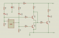
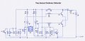
Please check my attached schematic.
This is more of a learning circuit for me so I'm trying to figure out a few things.
I've got the LM393 comparator part of the circuit working great thanks to many members of this forum. Now I'm trying to switch on an LED only when both LDRs detect darkness at the same time. I thought I would use one of the TTL NOR GATE circuits supplied by a kind member of this forum but there's a small hitch.
The output at the LM393 pins 1 and 7 (o/p) drops from 7.53V when in the light to 373mV when in the dark. However, when I connect the base of Q7 and Q8 to pins 1 and 7, Led's D4 and D5 light up slightly. The NOR GATE works fine but I'm trying to avoid led's D5 and D4 from lighting up.
I stepped up R4 and R5 to 1K, did not work. I also tried swapping around the position of R4 and R5 with their connected leds but, did not help?
Can somebody please tell me why this is happening and how can I avoid it.
Thanks a lot -JDR04
Attachments
-
 93.3 KB Views: 18