 Facebook
 Google
 GitHub
 Linkedin
Hello all. I am using the XM3425 power module from Wolfspeed, data sheet here: https://www.wolfspeed.com/products/power/sic-power-modules/xm3-power-module-family/cab425m12xm3/
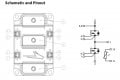
It is composed of multiple parallel connected FETs. In the connection diagram, there is a 4-pin connector - two for the gate, and two for the source. Unfortunately, on my PCB, only one of these has been connected to source, with the other one intended to be used for the source left unconnected.
Of course, there is no information regarding how the devices are connected internally, but as a sanity check until I get back to the lab tomorrow, I wanted to know if anyone had any opinions on whether this would cause any issues. It is not clear whether all sources of the devices are connected together, such that it does not matter, or whether the sources are all common only when both of the pins are connected to the source plane on the PCB. Connection diagram attached.
I often see a single gate pin and a single source pin for high power SiC modules, so have yet to run into this issue before.
Attachments
-
 71.1 KB Views: 15


