Noisy Audio Output

Audioguru again

Joined Oct 21, 2019
6,826
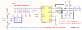
When bridged speakers are connected to a PAM8403 then a POP occurs during power-up if the pin8 Vref capacitor value is small like you have. Try 1uF or 10uF.
With headphones that cannot be bridged then the coupling capacitors feeding them might also cause a POP if the Vref capacitor is small.
 

Thread Starter

kemuelgersonb

Joined Mar 18, 2019
34
When bridged speakers are connected to a PAM8403 then a POP occurs during power-up if the pin8 Vref capacitor value is small like you have. Try 1uF or 10uF.
With headphones that cannot be bridged then the coupling capacitors feeding them might also cause a POP if the Vref capacitor is small.
Thanks for this info. Will update you as soon as I tested it.
 

Thread Starter

kemuelgersonb

Joined Mar 18, 2019
34
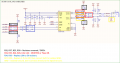
All, just to update I managed to make it work by isolating the output's jack GND and connecting it to the LN and RN of the amplifier's output with 22R resistor. Did some component removal also on the passive D to SE network. Thank you.
 

Audioguru again

Joined Oct 21, 2019
6,826
"isolating the output's jack GND and connecting it to the LN and RN of the amplifier's output with 22R resistor".
I guess that LN and RN are the -OUT L and -OUT R that should never be shorted together because they are speaker outputs.
The speaker outputs are bridged so that each speaker wire is driven with Its own power amplifier.

Your headphones cannot connect to bridged outputs because their left and right earphones have a common ground. Each earphone must have a series capacitor to block the DC on the amplifier outputs as shown in bottom half of post #15.
 

Audioguru again

Joined Oct 21, 2019
6,826
1) Why are R34 and R36 5k ohms when the datasheet says 18k minimum?
2) Why do you still have R27 and R29 making a "pseudo ground" that is not needed?
3) Why are R16 and R20 shorting the outputs to ground?
4) Why did you still have C42 and C47?

I attach your modified schematic what I guess you have now:
 

Attachments

MisterBill2

Joined Jan 23, 2018
27,809
I SEE A VERY MUCH HIGHER frequency on that wave form scope trace. And I see outputs tied to each other in the circuit diagram,. WRONG!! NEVER tie differential outputs together.
Are those speaker outputs or just what are they?? Try using only one of them, leave the other open, and see what you get.
Also, those capacitors across the output are there for a reason, they should not be removed or bypassed. They are there to filter out that high frequency signal. So OF COURSE!, if the noise filter is removed then the noise will stay.
 
Last edited:

Audioguru again

Joined Oct 21, 2019
6,826
You never overload the 260kHz PWM at the output of the class-D amplifier with a 1uF capacitor that has a reactance of only 0.6 of an ohm. The datasheet shows LC filters instead.
 

MisterBill2

Joined Jan 23, 2018
27,809
I see another problem toward the input side,which is that the differential outputs, AU-HPRN and AU-HPRP are connected so that the signals cancel and only the noise remains. At least that is what shows in the drawing provided. When the two phases of a differential signal are summed, as is done in the figure, what remains is the common mode voltage, which is what using the differential circuit is intended to cancel. So if those lines really are a differential signal pair, the signal is cancelled and the noise remains. It is not at all a "passive bridge" circuit, it is a signal cancelling circuit, with the common-mode signal remaining.
 

Audioguru again

Joined Oct 21, 2019
6,826
I see another problem toward the input side,which is that the differential outputs, AU-HPRN and AU-HPRP are connected so that the signals cancel and only the noise remains. At least that is what shows in the drawing provided. When the two phases of a differential signal are summed, as is done in the figure, what remains is the common mode voltage, which is what using the differential circuit is intended to cancel. So if those lines really are a differential signal pair, the signal is cancelled and the noise remains. It is not at all a "passive bridge" circuit, it is a signal cancelling circuit, with the common-mode signal remaining.
The differential to single-ended inputs problem was fixed in the last schematic by removing "N signals" from R32 and R37.
 

MisterBill2

Joined Jan 23, 2018
27,809
ONE MORE THING that is bothersome is that back in post #1 the one waveform already has a bunch of high frequency on it, while the other does not. And we have not much reference as to just what that input signal looks like after that. At least I don't think that there is. So that seems to be one issue because with a good amplifier the output is just a bigger copy of the input, so noise in gives more noise out.
Next, the amplifier used is not a headphone amp, it is intended to drive speakers differentialy. So it might be that the noise is a common mode artifact that is not present across the differential output. In that case one option would be to use the series resistors from each output negative to the jack common. The 2r7K is large enough to avoid damage to the amplifier.
A better choice will be to have each output drive a transformer, so that the one side of the secondaries may be safely tied.
Another option is to use an amplifier intended to drive headphones with a common return line. Those do exist, but they do not deliver so much audio power.
The very simplest choice is to replace the present 3-wire headphone cord with a four conductor cord and isolate the two headphones. Of course that also requires a much greater soldering skill. The four conductor cords and plugs are common on the headsets that include microphones, and so the cords with molded on connectors are available.
 

seanstevens

Joined Sep 22, 2009
323
Class D amps are noisy beasts. Some manufacturers claim no filter is needed or minimum ferrites but depending on where the device is used and the required quality of output sound, most likely they would need a low pass filtering the output. Your second trace of the scope clearly shows this noise...
 

Audioguru again

Joined Oct 21, 2019
6,826
In the first post, the differential signals at the inputs and outputs are connected together then they should completely cancel.
The amplifier manufacturer claims that the class-D PAM8403 amplifier " It offers low THD+N, allowing it to achieve high-quality sound reproduction".
They say, "Not recommended for new design" so maybe it has noise problems.
 

MisterBill2

Joined Jan 23, 2018
27,809
The device, the class-D PAM8403 amplifier, may indeed produce a constant low level noise that would not be noticed in the intended automotive sound system application. But that same constant noise level would be a large portion of a headphone-level output. In that case there is no way around the noise problem.
So I suggest finding an amplifier designed to drive headphones. Certainly there are many of them around.
 

Audioguru again

Joined Oct 21, 2019
6,826
The class-D PAM8403 amplifier was made for portable amplified speakers, not cars since its recommended supply is only 2.5V to 5.5V.
Its bridged outputs produce only 0.33W into 8 ohms or 1W into 4 ohms per channel at low distortion with a 3.3V supply. It produces 3.2W into 4 ohms per channel with severe clipping distortion with a 5V supply.
 

Thread Starter

kemuelgersonb

Joined Mar 18, 2019
34
The class-D PAM8403 amplifier was made for portable amplified speakers, not cars since its recommended supply is only 2.5V to 5.5V.
Its bridged outputs produce only 0.33W into 8 ohms or 1W into 4 ohms per channel at low distortion with a 3.3V supply. It produces 3.2W into 4 ohms per channel with severe clipping distortion with a 5V supply.

Sorry where did you get that info? I am using a 16 ohms headset. Any ideas how to measure a clean sine wave output? Do I need a LPF?
 

LowQCab

Joined Nov 6, 2012
5,101
You can't use any "Bridge-Amp" with only 3-Wires,
regardless of whether it's a Digital, or, Analog, Amplifier.

All Headphones that I know of only use 3-Wires.

If You want more Volume .............
You will need to supply more Voltage to ANY type of Amplifier that You want to use.

A simple and cheap "Dual-Op-Amp" will blow your ears off "if" You Power it with at least ~12-Volts,
and do it with extremely Low-Distortion, ( if You choose a high-quality Op-Amp ).
.
.
.
 
Top