Noisy Audio Output

Thread Starter

kemuelgersonb

Joined Mar 18, 2019
34
Hello,

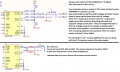
I am wondering what can be done to eliminate the noise in the audio output with my circuit below.
The main DSP is from Airoha and I coupled it with PAM8403 driver, and I used a passive differential to single ended
bridge to connect the audio. It is not working when the P and N nodes of audio are connected both.
1654090685524.png
1654090650075.png
Here's my oscope capture for Left and Right (single ended only) input to PAM.
1kHz at 0dBm played thru BT streaming.
1654090826989.png
 

Attachments

LowQCab

Joined Nov 6, 2012
4,023
Not enough information ...............

Do You have noise with the inputs shorted to Ground ?

Why are several Output Filter Components "X-ed-out" ?,
this looks like a Digital-Switching-Amplifier,
the Filter-Components are probably there for a good reason,
all of them.
Is your Output-Filtering set up exactly as per the manufacturers recommendations ?

What is BT Streaming ?, and what does "played-through" mean ?
Proper testing requires eliminating as many variables as possible.

Has your Sine-Wave-Source been verified to be clean and quiet ?

Will your Amplifier perform properly with no-Load ?,
are You providing a proper Load when testing ?

Have You actually tried listening to Music with Your Amplifier ?
.
.
.
 

Thread Starter

kemuelgersonb

Joined Mar 18, 2019
34
Not enough information ...............

Do You have noise with the inputs shorted to Ground ? - to be tried

Why are several Output Filter Components "X-ed-out" ?, - those are provisions and will explore to mount it later
this looks like a Digital-Switching-Amplifier,
the Filter-Components are probably there for a good reason,
all of them.
Is your Output-Filtering set up exactly as per the manufacturers recommendations ? - yes it is based on datasheet, but it needs to be fine-tuned in actual

What is BT Streaming ?, and what does "played-through" mean ? - I flashed it with a FW that allows me to do bluetooth streaming using my mobile phone, and the sine wave input is played from it.

Proper testing requires eliminating as many variables as possible.

Has your Sine-Wave-Source been verified to be clean and quiet ? - yes

Will your Amplifier perform properly with no-Load ?,
are You providing a proper Load when testing ? - I am using a headphone 3.5mm

Have You actually tried listening to Music with Your Amplifier ? - yes tried it but it very noisy (mostly digital)
.
.
.
Thank you for the follow-up questions :)
 

Thread Starter

kemuelgersonb

Joined Mar 18, 2019
34
It is a bridge-tied-load amplifier, so the Left speaker connects between +OUT_L and -OUT_L, and the Right speaker connects between +OUT_R and -OUT_R.
See the diagram on the datasheet
https://www.mouser.com/datasheet/2/115/PAM8403-247318.pdf
if you connect +OUT to -OUT then there won’t be any output signal.
On the input side when all of the resistors are populated (R32/33, R35/37) they cancel the audio signals out, so I omitted one for each differential nodes. Seems the passive converter is not working, same goes on the output side.
 

sghioto

Joined Dec 31, 2017
5,380
Then maybe it's in the design of the pc board.
How are the grounds for the power and audio routed?
Have you tried shorting the inputs to ground as mentioned earlier?
 

Audioguru again

Joined Oct 21, 2019
6,673
I agree that by mixing the bridged outputs cancels the signals.
The datasheet says that the minimum allowed input resistors is 18k but yours are 10k.
 

Thread Starter

kemuelgersonb

Joined Mar 18, 2019
34
1) Changed R34/36 from 10k to 18k - volume went up
2) Applied EMI filters at the output - still the same
3) Shorting audio input (R31/38) MCU reboots - no good

NB : Seems the output now is distorted as I can have a clean signal / music somewhere at 50% of the total volume when music streaming.
 

Audioguru again

Joined Oct 21, 2019
6,673
The PAM8403 amplifier is class-D that has its outputs switching at 260kHz. That is what is shown on your oscilloscope, not noise.
Your schematic shows a 33V power supply that will explode the PAM8403 power amplifier. Use 3.3V instead.
You show too many parts that will not work.
 

Attachments

Thread Starter

kemuelgersonb

Joined Mar 18, 2019
34
The PAM8403 amplifier is class-D that has its outputs switching at 260kHz. That is what is shown on your oscilloscope, not noise.
Your schematic shows a 33V power supply that will explode the PAM8403 power amplifier. Use 3.3V instead.
You show too many parts that will not work.
The PAM is operated at 3.3V.
Q : Why do you need that large DC blocking cap? I thought this amp is supposed to be filterless?
(How did you estimate the blocking cap value?)
 

Audioguru again

Joined Oct 21, 2019
6,673
The 250uF capacitors block the DC at the outputs but pass frequencies down to 20Hz into 32 ohms headphones.
Each output is at half the DC supply voltage so that they can swing symmetrically up and down. The DC might destroy your headphones and will push the voice coil and membrane over to one side causing severe distortion.

The calculation for a coupling capacitor is 1 divided by (2 x pi x R x f). Then 1/(2 x 3.142 x 32 ohms x 20Hz)= 249uF. 20Hz will be at -3dB which is half the power of high frequencies.
If you do not like deep bass then use 22uF.
 

Thread Starter

kemuelgersonb

Joined Mar 18, 2019
34
The 250uF capacitors block the DC at the outputs but pass frequencies down to 20Hz into 32 ohms headphones.
Each output is at half the DC supply voltage so that they can swing symmetrically up and down. The DC might destroy your headphones and will push the voice coil and membrane over to one side causing severe distortion.

The calculation for a coupling capacitor is 1 divided by (2 x pi x R x f). Then 1/(2 x 3.142 x 32 ohms x 20Hz)= 249uF. 20Hz will be at -3dB which is half the power of high frequencies.
If you do not like deep bass then use 22uF.
thank you for that clarification. however this product can also be used by other auxiliary passive speakers with 8 ohms load. 250uF
would limit that potential no?
 

Audioguru again

Joined Oct 21, 2019
6,673
Headphones have one side of each channel connected to 0V so they need output coupling capacitors.
The PAM8403 has "bridged" channels with each wire of the speakers driven with opposing signals then output coupling capacitors are not needed.
 

Thread Starter

kemuelgersonb

Joined Mar 18, 2019
34
Headphones have one side of each channel connected to 0V so they need output coupling capacitors.
The PAM8403 has "bridged" channels with each wire of the speakers driven with opposing signals then output coupling capacitors are not needed.
Alright I will try it. How about popping sounds during power up, it is audible also. I will check if it be eliminated in the process.
 
Top