Noise problems in industrial setting

Thread Starter

signalflow

Joined Mar 12, 2014
50
Anyone know the best most effective way to filter out contactor noise and AC motor noise on board? The noise is coming in through at least 2 ways: 1) through the step-down transformer that powers the circuit and 2) through the relays driving the AC motors, etc.

I am powering 240V contactors and AC motors and using the same 240V lines through a step-down transformer and simple switcher power supply to power 5V and 3.3V chips.

The problem is that I get a lot of electrical noise in the system when the contactors turn on or off and when the AC motors turn on/off.

I am running the stepped-down power lines through a common-mode choke. I also have bidirectional TVS diodes across the stepped down voltage and from 5V to gnd and 3.3V to gnd...but still getting noise problems.

Thanks for any help.
 

Thread Starter

signalflow

Joined Mar 12, 2014
50
I have flyback diodes across the relay coils. I also have RC snubbers across the contactor coils. I do not have snubber across the AC motors though. The chassis of the AC motors are all grounded to earth ground.

What kind of capacitors do you recommend using before and after transformer? Ceramic? What values do you recommend? Just a ballpark range?

I see you have capacitors between the 2 lines (differential mode) and then capacitors from each line down to earth ground (common mode filtering). I currently do not have any earth ground connections after the transformer (secondary side). Do you think this could be causing problems (can the common mode choke work without a connection to earth ground for return)?

Thanks.
 

#12

Joined Nov 30, 2010
18,224
This is a very problematic situation. An advanced level designer/troubleshooter might look at it and know what to do...and he might not. In a lot of cases, the absolute minimum is, "eyes on the situation". My drawings are only a suggestion and the results of using them might be worthless. However...

There are capacitors for use at power line voltages and they are rated exactly for that purpose. They are usually .1 uf and they use the inductance and resistance of the powers wires as part of their filtering equation. On the low voltage side, something between .01 uf and 1 uf (.1 uf +/- a factor of 10) usually helps. Ceramic or poly film capacitors are good for this job.

What to do about Earth ground is beyond the scope of what I can speak to without being there in person.
 

MaxHeadRoom

Joined Jul 18, 2013
30,807
I see you have capacitors between the 2 lines (differential mode) and then capacitors from each line down to earth ground (common mode filtering). I currently do not have any earth ground connections after the transformer (secondary side). Do you think this could be causing problems (can the common mode choke work without a connection to earth ground for return)?

Thanks.
I have designed and installed many custom installations over the years and have always prescribed to the earth grounding of supplies, and never had a problem, many of these have been PC based systems where the PC as normal has a grounded DC supply, many espouse galvanic isolation, but there is always the possibility of inductive/capacitive coupling, as far as noise is concerned.
Most are installed in harsh industrial settings.
Max.
 

Thread Starter

signalflow

Joined Mar 12, 2014
50
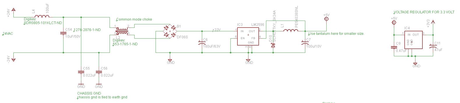
OK, I put an LC filter with a cutoff of 5KHz just after the secondary side of transformer (24 VAC). Then I put a 0.022uF cap from one line to earth gnd and another 0.022uF cap from the other line to earth gnd. Then the two lines go through a common mode choke, rectifier, then voltage regulators.

I am still getting noise coming in through the power lines.

My digital gnd is floating relative to earth gnd. Should I tie my digital ground to earth ground as well? By digital ground, I mean what my 5V is referenced to and what all of the ICs use.

Any other ideas how to filter out the noise coming in through power supply?

Thanks.
 

Thread Starter

signalflow

Joined Mar 12, 2014
50
Here is the schematic. L4 and C54 form the LC filter with cutoff of 5KHz. C55 and C56 are the new caps going to chassis (earth) gnd.


Thread Starter

signalflow

Joined Mar 12, 2014
50
I disconnected all of my digital inputs (monitoring switches) and disconnected my relay board and the noise stopped getting in as far as I can tell. So the power supply schematic above appears to work. Now I just need to figure out how to filter the noise out of the digital inputs and the relays.
 

THE_RB

Joined Feb 11, 2008
5,438
OK, I put an LC filter with a cutoff of 5KHz just after the secondary side of transformer (24 VAC). Then I put a 0.022uF cap from one line to earth gnd and another 0.022uF cap from the other line to earth gnd. Then the two lines go through a common mode choke, rectifier, then voltage regulators.
...
Everything you put between the mains transformer and the bridge rectifier was a complete waste of time and parts. :)

The mains transformer inductance is so incredibly large you won't get any significant noise coming out the secondary.
 
Top