Noise passing through filters when mounted on signal.

Thread Starter

Manu Sisko

Joined Sep 24, 2018
10
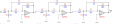
Hello. I've constructed a circuit to sample, amplify and filter the signal from a photopletysmograph (a photodiode and an IR led). The IR led gets modulated at 1600 Hz by a 18f2550. The photodiode signal is amplified with a transimpedance amplifier and the resulting signal goes through a PassBand MFB 3 staged Filter (Pass band being 1400 - 1800 Hz). The filter frequency response is perfect, as I've tested it separately. My problem is the following. If any kind of noise get coupled with my 1600 Hz signal modulation (as if, a 50 Hz mains hum mounted on top of my signal, or any other frequency regardless), then this noise passes through the filters cleanly, withouth attenuation, even though it is far into the stop band. I've shielded the circuit, and tested the noise without signal, which ended up being negligible. I don't have a ground plane on my pcb (I'm using single supply and the filtering stage is referenced to Vcc/2 buffered by an op amp). What could be causing the filters to allow the noise to pass when coupled with the signal??

Note: My circuit doesn't show any de-coupling capacitors, but I've implemented quite a few of them with no apparent progress. The whole circuit has been shielded. The schematic is messy, as I couldn't find any Symbol for the MCP6004 that had separated Op Amps on Eagle.
 

Attachments

crutschow

Joined Mar 14, 2008
34,432
Here's the LTspice simulation of the filter with 50Hz riding on a 1600Hz signal and it suppresses the 50Hz signal at the output as expected (first simulation).

Does the filter's frequency response follow the expected attenuation (second simulation below)?

upload_2018-9-24_8-48-2.png
upload_2018-9-24_8-52-10.png
 

AlbertHall

Joined Jun 4, 2014
12,346
I don't know if this is the problem but any non-linearity in the circuit would generate the mixing products 1600±50Hz and those would pass through the filter easily.
 

Thread Starter

Manu Sisko

Joined Sep 24, 2018
10
Hello. Thanks for your replies!!

Here's the LTspice simulation of the filter with 50Hz riding on a 1600Hz signal and it suppresses the 50Hz signal at the output as expected (first simulation).

Does the filter's frequency response follow the expected attenuation (second simulation below)?

View attachment 160447
View attachment 160448
Yes, the filter has a similar response (it varies a little bit, I assume it's because of the variable component values). It should act according to the first simulation, but for some reason it allows the 50Hz through.

I don't know if this is the problem but any non-linearity in the circuit would generate the mixing products 1600±50Hz and those would pass through the filter easily.
What do you mean by non-linearities??
 

Thread Starter

Manu Sisko

Joined Sep 24, 2018
10
Any circuit that distorts the signal, even a little, is non-linear and will lead to the generation of new frequencies by the mixing of the input signals. It does not need to be designed specifically for this purpose.
https://en.wikipedia.org/wiki/Frequency_mixer
Interesting... I've been reading this article https://www.allaboutcircuits.com/te...als-without-a-multiplier-the-switching-mixer/
Apparently switching a signal at a given frequency is enough to mix such frequency... Which I'm essentially doing by modulating the IR Led that drives the Photodiode -> transimpedance amp. The resulting wave doesn't appear to follow a mixed pattern though, here's a pic from the filter's output, when zoomed out. The internal frequency is unchanged at 1600 Hz. How can I tell if I'm mixing the noise into the signal? And how could I resolve it?
 

Attachments

Thread Starter

Manu Sisko

Joined Sep 24, 2018
10
I've read through the post, they seem to have resolved it by enclosing the circuit in aluminum foil. I've installed a shielding with some differences:
- I cannot have the photodiode close to the transimpedance amp as it's meant to be a measuring device for the finger. I've the wires shielded as I've used a USB cable to connect it to the board.
- The shielding in my case is connected to earth ground, not supply ground. I've tried connecting them both but it seems to have no effect.
- I've both, my signals PCB, along with my PIC pcb and a small portion of a power control PCB (the optocouplers for driving solenoid valves) inside the shielding of aluminum foil. Should I keep the digital and analog boards in separate shieldings?

As a side note: I've tried modifying the modulation frequency to see the results: At 3.2kHz, there is absolutely no signal from the Photodiode going through the filters, but there is some offset produced EMI at a different frequency (I modulate the optocouplers somewhere around 4200 Hz, it would become 8400 Hz in this case as I modulate them with the same TIMER as the IR led). So it appears the 3.2kHz modulation gets mixed with the 8.4kHz EMI and passes through. However, when I slow down this TIMER (Having 800 Hz on the IR Led and 2100 Hz on the EMI modulation), there is a smaller signal from the Photopletysmograph but no offset caused by the EMI modulation. However, in this last scenario, the coupled noise from other sources seems much greater. I'm quite confused to be honest... It clearly seems like a mixing problem, and I'm not sure I can enhance the shielding any further.
 

Thread Starter

Manu Sisko

Joined Sep 24, 2018
10
Fingers are a very good source of mains frequency! Is the problem still present when the finger isn't?
Yes, the problem remains. Up to a recent point, if I didn't touch the shielding with my finger my amplifier/signal could tend to oscillate at low frequency (2 Hz ish). This got solved after fiddling around with the shielding/ground wires that connect the signal PCB to the PIC pcb.
 

crutschow

Joined Mar 14, 2008
34,432
How can I tell if I'm mixing the noise into the signal?
If the bottom and top peak are in phase, it's modulated.
If the bottom and top peak are out of phase, then it's just being added.

Here's a picture of a modulated wave:
upload_2018-9-24_17-53-0.png

Since the top and bottom peaks in the oscilloscope picture are out of phase, the low frequency signal is just being added to the high frequency signal, not modulated.
 

Thread Starter

Manu Sisko

Joined Sep 24, 2018
10
If the bottom and top peak are in phase, it's modulated.
If the bottom and top peak are out of phase, then it's just being added.

Here's a picture of a modulated wave:
View attachment 160477

Since the top and bottom peaks in the oscilloscope picture are out of phase, the low frequency signal is just being added to the high frequency signal, not modulated.
Yes, as I said the modulated signal is the photopletysmograph signal. The noise gets added (I refered to it as coupled) on top of it, and that resulting signal passes through the filter, which shouldn't happend.
 
Top