noise on micro controller pwm output

Thread Starter

mah

Joined Mar 15, 2010
393
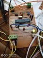
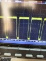
I used mega8 ADC to control duty cycle of pwm output but there is a little noise on pwm signal. I tried to reduce it using 100nf capacitor on inputs, there is caacitor on VCC. there is 1uf on AVref. the external crystal with its two capacitors are close to the mega. the noise increased when connect it to switch dc dc converter.I use the output voltage of the converter as analog input to the ADC of the mega, Is this the noise source?( because of ripple in dc converter) , How to reduce it?
 

BobTPH

Joined Jun 5, 2013
8,967
Explain what you nean by noise on the PWM output. This is a digital signal , noise should not matter much unless it is so large that the switch you are controlling goes on and off when it shouldn’t.

Or do you mean there is jitter in the duty cycle?

Bob
 

Wolframore

Joined Jan 21, 2019
2,610
You need to supply a circuit diagram which shows how everything is connected and what it’s connected to. Help us help you, otherwise we will play 50 questions or guess at possible issues. How did you determine you have spikes? Do you have an oscilloscope screenshot?
 

djsfantasi

Joined Apr 11, 2010
9,163
there is chattering in pwm signal, it isn't constant at 5v level there is spikes
How many PWM outputs are you using?

The Mega has several PWM outputs. But having several outputs does not mean they should all be used. Or used without compensating for multiple outputs.

The biggest advantage of multiple outputs is the ability to have options in a complicated system; where there may be pin conflicts.

Even on a smaller ATMega processor, there are limits. It often shows up when driving multiple RC servos without a coprocessor board. You may be able to drive more than 2 servos, but you shouldn’t. They won’t operate reliably.

Multiple PWM outputs share the same clock. When there are more uses of the clock, reliable calculations are not possible.

When I need more than 2 PWM outputs, in any form, I add the servo shield to the Arduino. This gives you 16 reliable PWM outputs using a coprocessor.
 

MisterBill2

Joined Jan 23, 2018
18,509
I see a much higher frequency on the signal at both the high and low stated. Probably you can get a much clearer view of it with a much higher sweep speed. That signal appears to have a constant amplitude as well. That may even be due to the ground reference connection point of your scope probe.SO I suggest probing the supply voltages because it does not seem to be random noise at all. It is a signal from some part of your circuit. OR it could be an outside broadcast radio station. That was a problem at one place where the lab area was about 500 feet from a 20KW AM radio broadcast tower.
 

jpanhalt

Joined Jan 18, 2008
11,087
You may be seeing noise from an oscillator introduced into the power rails (Does the PWM use the same power source?). What sort of decoupling capacitors do you have on the MCU?
 

MisterBill2

Joined Jan 23, 2018
18,509
In the first photo that is about 300 millivolts of noise, in the recent photo the display scale makes it very hard to see the noise, but it is still obvious on the low part of that square wave. If we see the waveform with a half a vlot per division we will much better be able to see how much noise voltage remains.
 

Thread Starter

mah

Joined Mar 15, 2010
393
You may be seeing noise from an oscillator introduced into the power rails (Does the PWM use the same power source?). What sort of decoupling capacitors do you have on the MCU?
Yes there is 10uf and 100nf on mcu vcc. The noise came when I connected to the two pwm why?
 
Top