noise on micro controller pwm output

MisterBill2

Joined Jan 23, 2018
28,133
everyone is still guessing without a clear circuit diagram and exactly what’s being switched..
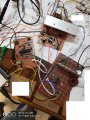
I have seen incorrect ground connections create similar traces, and that is why I made that suggestion. AND I have used a lab that needed a screen room to reduce the interference from the nearby AM broadcast station. So they are not just guesses they are valid possibilities.
 

jpanhalt

Joined Jan 18, 2008
11,087
It looks like you have some decoupling on the gate drivers to their 12V supply, but not on the MCU power pins, which are not shown.
 

Thread Starter

mah

Joined Mar 15, 2010
393
I see two pwm controlled power supplies in parallel. I see no way for the circuit to function in a satisfactory manner.
the first converter is boost converter and it delivers power to buck converter which is connected to resistive load.
 

Wolframore

Joined Jan 21, 2019
2,619
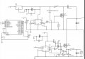
Here’s the schematic. Could you please explain your expectations of the circuit? Is there a reason why you have two switching supplies tied together at their outputs? What is the expected output value?
45F43C44-885F-46B3-8718-6D50D9BAD10F.jpeg
 

MisterBill2

Joined Jan 23, 2018
28,133
I am very confused as to why there are two power supplies connected, either in series or in parallel. What is the expected benefit, and what is the desired output, voltage and current? Please explain that for us.
 

Thread Starter

mah

Joined Mar 15, 2010
393
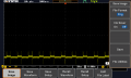
I am trying to cascade two converters regardless of their type or function. there are stability problems due to cascading converters and i am working on it. now this is the output of the boost converter when coupled to the buck converter, how ever each converter work fine on its own.these noise doesn't appear on computer with ni daq. when i reversed the two converters and measured the output of buck converter that feeds boost converter it gives DS0002
 

Attachments

Last edited:

MisterBill2

Joined Jan 23, 2018
28,133
I understand what is being done, and certainly there would be stability problems. My question is why cascade converters? There also exists buck/boost topology and so there is no need for cascading converters.
 

Thread Starter

mah

Joined Mar 15, 2010
393
cascaded converters are used in Microgrids and dstributed power systems. in DC Microgrid you can have different voltages buses, 100v bus,48 v bus and 24volt bus. so they are needed. now I think i have high frequency noise and i don't know its source or how to remove it without affect stability.
 

MisterBill2

Joined Jan 23, 2018
28,133
I am sure that those power buses are very well stablized and by passed, and the common is a very low impedance path. In addition it is not likely that the voltage from each regulator is controlled by a logic module. So by using a processor to control them you have an entirely different situation.
And in the experimental circuit probably the signal return current is using the same common as some part of the power circuit.
 

Thread Starter

mah

Joined Mar 15, 2010
393
I found few points connected to grounds more than one time, when I removed the connection the noise was reduced. But the output of the boost converter is still has noise
 

Thread Starter

mah

Joined Mar 15, 2010
393
Yes it is less but when I connect it on c6 it is high. I need to measure the output on c6 not c11 and I need it clear
 

MisterBill2

Joined Jan 23, 2018
28,133
Yes it is less but when I connect it on c6 it is high. I need to measure the output on c6 not c11 and I need it clear
I was thinking that C11 was across the final output. Do you mean that there is a noise voltage seen when you put the scope input directly across the terminals of C6 as well?
One more thing is that if you use a much faster sweep speed you should be able to actually see that signal, which I think is a square wave at the switching frequency of one of the regulator circuits.
 

MisterBill2

Joined Jan 23, 2018
28,133
Yes,there is noise on c6. What do you mean by fast sweep? How to do it?
A fast sweep in this case would be a high enough sweep speed so that only one of the pulses would be on the screen. That should expand the trace enough so that the noise frequency can be determined. Knowing the noise frequency will allow you to determine where it is coming from, which is the first step in knowing how to eliminate it.

I was thinking that the voltage across C6 was the intermediate bus voltage, and that the voltage across C11 was the load voltage. It still looks that way to me.
 

Thread Starter

mah

Joined Mar 15, 2010
393
yes, c6 is the intermediate and what follow c6 is all a load so i need to measure on c6.
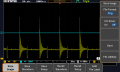
I measured the attached signal on c6
 

Attachments

MisterBill2

Joined Jan 23, 2018
28,133
OK, and that trace is interesting because I see spikes that appear to be a bit over 3 volts, with a very fast rise and fall time. Was that voltage actually present at the terminals of C6, a 200microfarad capacitor? Or in some part pf the circuit nearby?
Certainly that is a very regular waveform, which looks like it may be caused by the second regulator . And does this signal include the zero voltage point? If this signal is a DC voltage, what is that voltage? Now I am seeing that there is a lot of information that we do not have.
AND, i find it amazing that spikes of that magnitude exist directly across a 200 microfarad capacitor.

Something seems very wrong with the whole picture now.
 
Top