Facebook
 Google
 GitHub
 Linkedin
Hiya all,
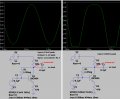
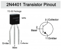
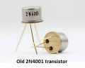
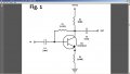
Decided to build my very first distortion pedal and found this easy-to-follow DIY guide with schematic and all (attached here); the circuit needs a 2N3904 transistor, two 104 capacitors and three 1/4-watt resistors (470R, 68K and 2.2M). As I couldn't find all the exact same components, I bought a 2N4001 instead as well as 1/2-watt resistors. I'm in the breadboarding phase (see attached photo) and I've double checked everything from properly identifying the CBE terminals to continuity issues using my multimeter, battery charge if full, guitar/amplifier connections, settings, etc. OK. I'm assuming the problem lies with those 1/2-watt resistors although I don't understand the reason why there's no sound at all when signal goes through the circuit...
Any help would be greatly appreciated.
Attachments
-
 101.1 KB Views: 63
 -
 52.9 KB Views: 56