NiMh & NiCd 1.2/1.5V Charger Schematic

crutschow

Joined Mar 14, 2008
38,621
R4 needs to be in series with the LM317 output to limit the current.

Note that using the transistor base-emitter voltage as a reference to stop the charge, gives about a 0.3%/°C change in that voltage.
Better to use a programmable reference, such as the 1.25V TLV431.
 

Alec_t

Joined Sep 17, 2013
15,145
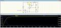
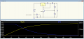
The regulation part of the post #20 circuit doesn't behave as you describe. Here's an LTspice simulation, with the cell modelled as a 1Farad capacitor :-
1766851980188.png
 

Attachments

crutschow

Joined Mar 14, 2008
38,621
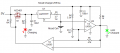
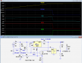
And my take, using a TLV431 1.25V adjustable reference with the LM317 regulator for an accurate, stable cutoff voltage (LTspice sim below):

Q1 and D3 allow the LM317 ADJ pin to be pulled down to about 0.25V by U2 to give a 1.5V output when the charge voltage limit is reached, since the minimum cathode operating voltage (K) of U2 is about 1.2V.
(The D3 LED is just to get a 1.4V forward drop. Its current is not high enough to emit any significant visible light).

The Red and Green indicating LEDs can be controlled by one transistor, since the forward drop of the Green LED is higher than the Red, so when the transistor is saturated ON, only the Red LED lights, and of course, when the transistor and thus Red LED is off, only the Green LED lights.

In operation, U2 is off (non-conducting) during charging since V(Ref) is below 1.25V, so V(K) is high from the current through R6..
This switches Q1 fully ON so that R4 sees the 1.25V reference voltage that LM317 generates across it, which determines the charge current.
This high voltage also turns on Q2, thus illuminating D1.

When U2's V(Ref) reaches 1.25V (1.5V Out), it turns ON, pulling V(K) low, so that Vadj is 0.25V which limits V(Out) to 1.5V and stopping the charge current..
This also turns off Q2, setting D1 off and D2 on.

1767043333579.png
 
Last edited:

Thread Starter

AnthonyB

Joined Nov 12, 2015
17
And my take using a 1.25V TLV431 adjustable reference with the LM317 regulator for an accurate, stable cutoff voltage (LTspice sim below):

Q1 and D3 allow the LM317 ADJ pin to be pulled down to about 0.25V by U2 to give a 1.5V output when the charge voltage limit is reached, since the minimum cathode voltage of U2 is about 1.2V.
(The D3 LED is just used to get a 1.4V forward drop. Its current is not high enough to get any significant visible light).

The Red and Green indicating LEDs can be controlled by one transistor, since the forward drop of the Green LED is higher than the Red, so when the transistor is saturated ON, only the Red LED lights and, of course, when the transistor and thus Red LED is off, only the Green LED lights.

View attachment 361248
Thank you so much for this ... methinks this is to be the build :)
 
Last edited:
Top