Newbie to electronics circuit confused

Thread Starter

bakhtal

Joined Aug 13, 2015
9
hi,

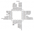
i am soldering my circuit which has Atemga 162 IC , in circuit diagram there are pin numbers 41,42,43,44 which is confusing part as in original datasheet of IC these pin do not exist.

i have programed the IC with flash hex file my question is whether pin numbers/sequence can get change from flash or program running inside IC ?

do i need to follow pin numbers as mentioned in diagram or should i follow function of pin like (PB0... RESET..) as you can see RESET in Diagram is mentioned at pin number 4 while in original datasheet its at pin number 9.


sorry for my ignorance am really confuse at this point i am attaching 2 photos please have a look and point me correct pin numbers or functions of pin to solder.
 

Thread Starter

bakhtal

Joined Aug 13, 2015
9
Oh my God :(
In Circuit Diagram ATmega162L-8AI has been used (44 pins just found on net)

while i have got and soldered ATMEGA162-16PU which has 40 pins 20 on each side.

i have also programed ATMEGA162-16PU with flash hex file made for ATmega162L-8AI , i am unable to find exact same ATmega162L-8AI IC for my circuit, is it possible i make use of my current IC ATMEGA162-16PU ?

what if i ignor pin numbers and connect my wires using pin functions like RESET is at pin number 9 in current IC, it wont make any damage right ?
 
Last edited:

Thread Starter

bakhtal

Joined Aug 13, 2015
9
Can i use ATMEGA162-16PU instead of ATmega162L-8AI ?

ATMEGA162-16PU programed with flash hex file that is compiled for ATmega162L-8AI does this make difference ?

can i solder according pin functionality ? ignoring pin numbers ...?
 

DerStrom8

Joined Feb 20, 2011
2,390
Yes, you can go by pin functions rather than pin numbers. However, the programming will probably need to be different. Does the hex code you burned to the 40-pin DIP version work? Have you been able to test it yet? You may need to edit the code before loading it onto the chip.

The ATMEGA162L-8AI is a surface mount chip that is difficult to prototype with. If you can edit your code to work on the -16PU, then you should be good to go :)

Matt
 

Thread Starter

bakhtal

Joined Aug 13, 2015
9
hi,

i just solder -16PU according to pin functions but its not functioning as correctly, i have source code (for ATMEGA162L-8AI) if you guys can plz edit it for ATMEGA162-16PU i will really appreciate ... soldering 16PU is easy as 8AI got too small pins and i am unable to find it from stores.

Here is Original Circuit:


Following is the code sorry i am unable to attach as file;


Code:
;// set AVR M162 fuses SUT1,SUT0,CKSEL3,CKSEL2,CKSEL0 and set BODLevel2
;// Fast Startup Time - Internal Clock 8MHz and BOD set level for 2.3v
;// Remember to set fuses = 0
;// UART 0 is to read CAM data goimg to CARD  Boot ATR is 12100 and Data after is 100 000 BAUD
;// Data flow is Inverted and Byte is sent MSBit first - also data MUST be checked for FRAME errors

;BAUD rate finding by changing UBBRL
;ATR= 3F FF 14 25 03 10  80  41 B0 02 69 FF 4A 50 70 80 00 58 38 01 00  14
;95 = FE FF 18 2B 06 01 FF 81 FF 42 A1 05 62 FE 45 40 61 81 00 51 31 03 00 FF 18
;92 = FE FF 10 27 02 11 FF 81 FF 40 B1 03 6A FE 49 50 71 81 00 59 39 01 00 FF 14
;90 = FF FF 14 25 03 10 FF 80 FF 41 B0 02 69 FF 4A 50 70 80 00 58 38 01 00 FF 14
;89 = FF FF 14 25 03 10 FF 80 FF 41 B0 02 69 FF 4A 50 70 80 00 58 38 01 00 FF 14
;88 = FF FF 14 25 03 10 FF 80 FF 41 B0 02 69 FF 4A 50 70 80 00 58 38 01 00 FF 14
;87 = FF FF 14 25 03 10 FF 80 FF 41 B0 02 69 FF 4A 50 70 80 00 58 38 01 00 FF 14
;86 = FF FF 14 25 03 10 FF 80 FF 41 B0 02 69 FF 4A 50 70 80 00 58 38 01 00 FF 14
;85 = FF FF 14 25 03 10 FF 80 FF 41 B0 02 69 FF 4A 50 70 80 00 58 38 01 00 FF 14
;83 = FF FF 14 25 03 10 FF 80 FF 41 B0 02 69 FF 4A 50 70 80 00 58 38 01 00 FF 14
;82 = FF FF 14 25 03 10 FF 80 FF 41 B0 02 69 FF 4A 50 70 80 00 58 38 01 00 FF 14
;80 = FF FF 14 24 01 10 3F 80 3F 40 B0 04 40 A6 FF 49 06 00 70 07 06 58 04 C4 00
;seems best is 87 averaged  now to play with Stop bits and Parity

;// UART 1 is to send out code at 115200 to PC for logging software


   .include "m162def.inc"


.cseg
.org 0
   jmp   RESET      ; Reset Handler


RESET:  
   ldi   r16,high(RAMEND); Main program start
   out   SPH,r16    ; Set Stack Pointer to top of RAM
   ldi   r16,low(RAMEND)
   out   SPL,r16

;// Logging CAM Data line
;// UART must be set using x2 clock for better accuracy
;// Read Data Line
USART_Init0:       ;CAM UART
   ldi   r16,(1<<U2X0)   ;Set x2
   out   UCSR0A,r16
   ldi   r17,0     ;Set baud rate
   ldi   r16,87     ;ATR is 12100  87  82 @ 8HMZ  164 @ 16MHz
   out   UBRR0H, r17
   out   UBRR0L, r16
   ldi   r16, (1<<RXEN0)|(0<<TXEN0)
   out   UCSR0B,r16   ; Enable receiver and transmitter 
   ldi   r16,(1<<URSEL0)|(1<<UPM01)|(0<<UPM00)|(0<<USBS0)|(1<<UCSZ01)|(1<<UCSZ00)  ;8E1
   out   UCSR0C,r16   ; Set frame format: 8data,even Parity, 1stop bit

;// UART must be set using x2 clock for better accuracy
;// Send to PC @ 115200 error 2,12%
USART_Init1:
   ldi   r16,(1<<U2X0)   ;Set x2
   out   UCSR1A,r16
   ldi   r17,0     ;Set baud rate
   ldi   r16,8     ;115 200  8 @ 8MHz  16 @ 16MHz
   out   UBRR1H, r17
   out   UBRR1L, r16
   ldi   r16, (0<<RXEN1)|(1<<TXEN1)
   out   UCSR1B,r16   ; Enable receiver and transmitter
   ldi   r16,(1<<URSEL1)|(1<<UCSZ11)|(1<<UCSZ10)  ;|(0<<USBS)
   out   UCSR1C,r16   ; Set frame format: 8data, 1stop bit

   ; Read 22 bytes ATR
wait_3F:
   ; Wait for data to be received
   sbis    UCSR0A, RXC0
   rjmp    wait_3F
   ; Get and return received data from buffer
   in    r16, UDR0
   ; need to rotate and invert byte
   ; 8 bits rotate
   ldi   r19,8
Rotate1:ror   r16
   rol   r17
   dec   r19
   brne   rotate1
   ; invert byte
   com   r17
   cpi   r17,0x3f
   brne    wait_3F
   ldi   r18,22
   rjmp   stor

main_uart:
USART_Receive:
   ; Wait for data to be received
   sbis    UCSR0A, RXC0
   rjmp    USART_Receive
   ; Check for Frame Errors
frame:   sbis   UCSR0A, FE0
   rjmp   read
   in    r16, UDR0     ;DUMMY Read to clear FE Flag
   rjmp   USART_Receive

   ; Get and return received data from buffer
read:   in    r16, UDR0

   ; need to rotate and invert byte
   ; 8 bits rotate
   ldi   r19,8
Rotate:   ror   r16
   rol   r17
   dec   r19
   brne   rotate
   ; invert byte
   com   r17

stor: 
USART_Transmit:
   ; Wait for empty transmit buffer
   sbis    UCSR1A,UDRE1
   rjmp    USART_Transmit
   out    UDR1,r17 
   dec   r18
   brne   main_uart


// Now to switch to 100 000  BAUD for CAM DATA and byte for byte XMIT
UART0_100:
   ldi   r17,0     ;Set baud rate
   ldi   r16,10     ;Data is 100 000 Baud @ 4.5MHz is 9
   out   UBRR0H, r17
   out   UBRR0L, r16


new_data:
; Wait for data to be received
   sbis    UCSR0A, RXC0
   rjmp    new_data
   ; Check for Frame Errors
frame100:
   sbis   UCSR0A, FE0
   rjmp   read100
   in    r16, UDR0     ;DUMMY Read to clear FE Flag
   rjmp   new_data

   ; Get and return received data from buffer
read100:
   in    r16, UDR0

   ; need to rotate and invert byte
   ; 8 bits rotate
   ldi   r19,8
Rotate_100:
   ror   r16
   rol   r17
   dec   r19
   brne   rotate_100
   ; invert byte
   com   r17

; Wait for empty transmit buffer
xmit_100:
   sbis    UCSR1A,UDRE1
   rjmp    xmit_100
   out    UDR1,r17

   rjmp   new_data
[\code]
 
Last edited:

Thread Starter

bakhtal

Joined Aug 13, 2015
9
hi,

Can somebody please edit source code ?

This source code is written for: ATMEGA162L-8AI

While i have got ATMEGA162-16PU :( i want to use ATMEGA162-16PU in my circuit as i am unable to find 8AI model IC.
 

DerStrom8

Joined Feb 20, 2011
2,390
Why can't you edit it? Did you copy and paste the code from someone else? If you're going to work with microcontrollers, I recommend you learn how to program them yourself. That's part of the process, otherwise you'll frequently find yourself lost, as you seem to be at the moment. It's not fun :p
 

Thread Starter

bakhtal

Joined Aug 13, 2015
9
hi,

sorry for my ignorance i am just a hobbyist and newbie to micro-controllers , i did not copy someone else code rather i downloaded it form internet along with circuit , i don't know assembly language that's why i can not find pins and register in this code to modify :(
 

blocco a spirale

Joined Jun 18, 2008
1,546
How does "downloaded it from the internet" differ from "copy" ?o_O

The problem is, there can be quite a lot of work involved in this kind of thing and anyone who gets involved would have to be prepared to bat it back and forth (unless they also build the hardware) until the bugs are fixed and I doubt anyone wants to do that.
 

Thread Starter

bakhtal

Joined Aug 13, 2015
9
oh ok , i thought it might be minor editing , i though just replace pin number or address in code :?

anyway thanks for helping and pointing in right direction, i guess i must find exact same type of IC.

You guys are great , really appreciate your help thanks again.

have a good day.
 

DerStrom8

Joined Feb 20, 2011
2,390
oh ok , i thought it might be minor editing , i though just replace pin number or address in code :?

anyway thanks for helping and pointing in right direction, i guess i must find exact same type of IC.

You guys are great , really appreciate your help thanks again.

have a good day.
Instead of trying to find the surface mount version of the microcontroller (difficult to prototype with, solder, etc) you should learn Assembly language so that you can program your DIP version.. That was my point--if you're going to work with microcontrollers, you'll need to learn how to program them yourself sooner or later. May as well start now.

And for the record, copying from the internet = copying someone else's code. They had to put it on the internet themselves, after all.
 

MaxHeadRoom

Joined Jul 18, 2013
28,619
oh ok , i thought it might be minor editing , i though just replace pin number or address in code :?
In all probability it is simple, obtain the reference man for both IC's and also compare the instruction set, I don't use ATMEL μp's but looking at the numbers I would think they are Very close most ways.
Max.
 

Thread Starter

bakhtal

Joined Aug 13, 2015
9
OK thanks for suggestions , i start learning assembly basics , code and instructions , will post my findings later.

Regards
 
Top