Newbie needs help: converting range hood lighting from halogen to LED

Thread Starter

lightpsycho

Joined Mar 21, 2018
18
Hey there,

I have some basic electrical knowledge and since the second out of two halogen bulbs on my range hood blew out, I thought it would be the time to replace those by 3W LED COBs (which are labelled as 12V AC or DC).

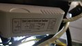
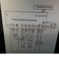
The original bulbs are 12V 20W G4 halogen bulbs. Looking at the schematics there's a transformer (of course) between the line feeding 120V AC and the processor board. So 2 wire in, but 3 wire out; one wire is going to 12V Hi-beam, another one going to 9.5V lo-beam, and the third one is neutral.

So, thinking I could do a direct swap, I pulled the old halogen and plugged the LEDs in. I see a flash of light, then nothing. Or so I thought. Taking a look at the bulbs, I could see a very faint light coming out. Pressed the light button again to switch to lo-beam and it got even dimmer. Well, the bulbs are functional. So I took my multimeter, pulled a bulb out a little, and metered at the pins. I had 0.9V....I was puzzled.

Then, reading a bit, I eventually remembered how LEDs suck so little current, and how the transformer inside my hood will most likely require to be replaced by a LED driver...!

First: am I right?

Second: If I am, then I have another question.

Since there is no such thing as a 3-wire output LED driver (that I know of), in order to preserve hi and lo beam function (without jumping the 12V and 9.5V wires and having only hi-beam), could I take:

1-3x1W (output voltage DC 3-11V 300mA) driver hooked up to lo-beam 9.5V considering 2.85W = 9.5V x 0.3A

and a

4-7x1W (output voltage DC 12-25V 300mA) drive hooked up to hi-beam 12V considering the leds draw a total of 6W @ 12V

Both of their neutral wires would be hooked up to the neutral terminal on the processor board (please see attachment). Does this make sense?
 

Attachments

Thread Starter

lightpsycho

Joined Mar 21, 2018
18
Replace the transformer for a led type ballast or led driver.
Indeed, that's what I want to do.

BUT, since the transformer has 3 wires, one neutral, one for 9.5V and one for 12V, and that there is no such thing as a 3-wire double output LED driver, I would be planning to use two drivers, rated for each of the respective voltages and sharing the same neutral. To me this makes sense....what do you think?
 

wayneh

Joined Sep 9, 2010
17,496
Indeed, that's what I want to do.

BUT, since the transformer has 3 wires, one neutral, one for 9.5V and one for 12V, and that there is no such thing as a 3-wire double output LED driver, I would be planning to use two drivers, rated for each of the respective voltages and sharing the same neutral. To me this makes sense....what do you think?
The outputs of the drivers will be in parallel and it may be problem to have power applied to the driver's output while it's not turned on. Keep in mind that the brightness of the LEDs will be proportional to the current driven through them. The voltage is irrelevant. So if your driver puts out 300mA when supplied 9.5V, it'll be just as bright as the 12V driver putting out 300mA.
 

sghioto

Joined Dec 31, 2017
5,380
BUT, since the transformer has 3 wires, one neutral, one for 9.5V and one for 12V,
Are you sure those voltages are coming straight off a transformer? If they are the LEDs should have work directly because the transformer would able to deliver over 3 amps to drive the halogen bulbs.
SG
 

Audioguru

Joined Dec 20, 2007
11,248
The output of a transformer is AC. 12VAC has a peak of 17V.An LED works only with DC. Maybe the AC or its peak destroyed the LEDs.
Maybe the LEDs need a current-limiting resistor and without one then they are destroyed.
 

Thread Starter

lightpsycho

Joined Mar 21, 2018
18
Are you sure those voltages are coming straight off a transformer? If they are the LEDs should have work directly because the transformer would able to deliver over 3 amps to drive the halogen bulbs.
SG
Kinda.

There's a transformer, which is then hooked to the processor board (see attached diagram in initial post). On the diagram, one of the positive wires is hooked to a terminal labeled as 12V, and another one labeled as 9.5V (both then point towards the sockets after the board). In reality, it's also how it is.

I managed to squeeze so time outta my tight schedule to snap a pic of the transformer this morning. We can clealy see the output has two positives and a negative. And also that they somehow decided to use two red wires for the mains input?!?!?
 

Attachments

Dodgydave

Joined Jun 22, 2012
11,285
That's an ordinary transformer with a dual output of 9V and 12V , ( transformers don't give out positive and negative they're AC driven) , if you want to use led lights then try a 12V led on the 9V rail for lower illumination, i personally don't think it will work, ideally you want a led ballast transformer with dimming facilities.
 

LesJones

Joined Jan 8, 2017
4,174
Looking at the block diagram in post #1 and the schematic of the transformer in post #9 it looks like the processor board must use triacs to switch the supply to the lights. (If it used relays then it should work with LED lamps.) I don't think the LED lights take enough current for the triacs to latch on after being triggered. I suggest trying the LED lamps connected directly to the transformer output. First try them connected to the white and yellow wires (12 volts) and then try them connected to the white and green wires. Can you trace out the schematic of the processor board between the transformer connections and the lamp connections ?

Les.
 

Thread Starter

lightpsycho

Joined Mar 21, 2018
18
That is very possible, the other possibility is the ET needs a minimum current.

See the pictures in post #11 of the thread I posted.
Yes I know, I also posted on that thread a lil bit as I found it after posting this one!

Looking at the block diagram in post #1 and the schematic of the transformer in post #9 it looks like the processor board must use triacs to switch the supply to the lights. (If it used relays then it should work with LED lamps.) I don't think the LED lights take enough current for the triacs to latch on after being triggered. I suggest trying the LED lamps connected directly to the transformer output. First try them connected to the white and yellow wires (12 volts) and then try them connected to the white and green wires. Can you trace out the schematic of the processor board between the transformer connections and the lamp connections ?

Les.
I do not have the knowledge to know the hows and whys, but I suspected that the leds aren't drawing enough current...

However, I read a report on another forum of a guy who replaced the transformer by a led driver; he connected both yellow and green to positive driver output, and white to negative, and he said it worked. He however lost hi and lo function, and the first two button presses switched the leds into hi mode (with 3rd press turning them off)...

I'll try to take the thing apart a soon as I can
 

ElectricSpidey

Joined Dec 2, 2017
2,758
It’s also a 50/50 chance that the LEDs do not pass current in both directions, and this causes a problem with the controller or the transformer. (depends on whether the manufacturer used a bridge or half wave)

Well, if that was the exact same model range, then the control panel does not use triacs to switch the light levels.

And…if the LEDs you have are AC/DC 12 volts you can use a regular transformer with a center tap to get a high and low. And you don’t actually need a driver. (although a driver might actually be cheaper, and allow you to dim)

Of course they may not work on 6 volts…
 

Thread Starter

lightpsycho

Joined Mar 21, 2018
18
It’s also a 50/50 chance that the LEDs do not pass current in both directions, and this causes a problem with the controller or the transformer. (depends on whether the manufacturer used a bridge or half wave)

Well, if that was the exact same model range, then the control panel does not use triacs to switch the light levels.

And…if the LEDs you have are AC/DC 12 volts you can use a regular transformer with a center tap to get a high and low. And you don’t actually need a driver. (although a driver might actually be cheaper, and allow you to dim)

Of course they may not work on 6 volts…
I remember looking at the other thread OP's pictures, and the coil was toroidal. I'm not too electronically inclined, but could that be why I see a 9.5V terminal on the diagram? i.e. the center tap is kinda off-center? lol...!

And indeed I have no way of verifying if the LEDs are going to work on 6 V...

Pardon my ignorance, but what if I were to try my initial suggestion? I'm just gonna quote myself:

[...]
in order to preserve hi and lo beam function (without jumping the 12V and 9.5V wires and having only hi-beam), could I take:

1-3x1W (output voltage DC 3-11V 300mA) driver hooked up to lo-beam 9.5V considering 2.85W = 9.5V x 0.3A

and a

4-7x1W (output voltage DC 12-25V 300mA) drive hooked up to hi-beam 12V considering the leds draw a total of 6W @ 12V

Both of their neutral wires would be hooked up to the neutral terminal on the processor board (please see attachment). Does this make sense?
 

ElectricSpidey

Joined Dec 2, 2017
2,758
There is no neutral output from a LED driver.

No, I don’t think that will work because both drivers are going to try and output 300mA.

You would need 2 Drivers that deliver different currents at the same output voltages, and be sure you could common one of the outputs.
 

LesJones

Joined Jan 8, 2017
4,174
If the processor board does not use triacs then it must use relays (Or it just routes wires to the light selector switches.) So if you connect the LEDs to the output of the board and use a normal transformer as ElectricSpidey suggests with it's 12 volts output to the connections on the processor board that had the white and yellow wires connected and a resistor between the connections where the green wire connected and the connection where the yellow wire connected then you should get the dimming you require. The resistor value will have to be selected by trial and error but I would suggest satrting with about 6 ohms (about 5 watts rating as it will be in a faily high temperature environment.
(I had not noticed that it was an electronic transformer. I just saw the symbol for a normal transformer on the picture.)

Les.
 

Thread Starter

lightpsycho

Joined Mar 21, 2018
18
If the processor board does not use triacs then it must use relays (Or it just routes wires to the light selector switches.) So if you connect the LEDs to the output of the board and use a normal transformer as ElectricSpidey suggests with it's 12 volts output to the connections on the processor board that had the white and yellow wires connected and a resistor between the connections where the green wire connected and the connection where the yellow wire connected then you should get the dimming you require. The resistor value will have to be selected by trial and error but I would suggest satrting with about 6 ohms (about 5 watts rating as it will be in a faily high temperature environment.
(I had not noticed that it was an electronic transformer. I just saw the symbol for a normal transformer on the picture.)

Les.
I metered at the transformer's output direct and it' now clear that it crapped out. I get 0.5 - 0.4V AC. No damage or dark spots are visible anywhere.

At this point, since this is a simple circuit board, I'm wondering if I could just replace everything except the coils...and start almost from scratch? I sincerely don't know what crapped out and maybe I could source better components than those that are on that PCB...? Could that be a viable option?

I'm including a pic of the board, again.
 

Attachments

Top