 Facebook
 Google
 GitHub
 Linkedin
Hi,
My name is Ian. I am 30 years old and this is my first post. I have a somewhat "decent" experience level with electronics but nothing too crazy. I am new to any type of microcontrollers, their code or wiring together motion control systems. I took a few electronics courses when I was @ PCT for automotive training and I have been doing car audio since age 12. So anyways, to my point:
I am trying to design an electronic control system for an automotive project. I want to be able to control the front-to-rear, hydraulic braking force bias from inside the car using an aftermarket hydraulic brake bias adjuster and a stepper motor system. I would like to use an absolute rotary encoder mounted in the car to make the adjustments and have a 24X4 LCD display that would display the current brake bias percentage.
Here are some concerns:
-Memory of Position: It would be important for the microcontroller to be able to keep the stepper motor in its current position with the vehicle being powered on or off and by my understanding the "Absolute" Rotary Encoder would be what I need. I would assume that with the use of an absolute rotary encoder and the fairly advanced ARDUINO MEGA 2560 REV 3 Microcontroller, I'd be able to code that in.
-Multiple-Complete Revolutions: Do most stepper motor drives, stepper motors and microcontrollers support, multiple, complete revolutions of the shaft? I know they can break down one complete revolution into a ton of steps but my hydraulic valve needs to be rotated completely, multiple times, is this something that I can do? I don't have the valve yet so I don't know how many turns it's adjustment knob takes from fully inward to fully outward but I would imagine in the neighborhood of 4-6.
-Stepper Motor Strength: The stepper motor I have chosen is a AUTOMATION DIRECT SureStep STP-MTRH-23079, its one of the larger on the market being a NEMA 23 frame but I can't get specs for output torque on any motors, only holding torque. I'd imagine the actual turning torque of the motor would be more or at least equal to the "holding torque". This motor is listed as 286 OZ. In. which converts to about 1.46 Ft. Lbs. I'm assuming this should be enough to turn the WILWOOD valve, but again, I don't have it on hand.
-ARDUINO MEGA 2560 REV 3, 5V Power Pin: The ARDUINO MEGA 2560 REV 3 has only (1) "5V" output pin. Is ok to wire this pin to multiple other pins like say the rotary encoder, stepper driver as well as the SunFounder Display?
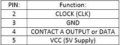
-Absolute Rotary Encoder Selection & Wiring: I chose a BOURNS EMS22A50-D28-LT6 Absolute Rotary Encoder. It has 6 Pins, most rotary encoders I have seen online are either a 4 for 5 pin. In my wiring diagram I only made 4 of the 6 connections, is this ok? It is my understanding that his particular rotary encoder does not have a center shaft "press in" button option but maybe I'm wrong, either way I don't need it. Here are the Pins I connected, followed by a pinout of all the pins on the encoder. So I didn't connect Pin 1 (Digital Input) or Pin 6 (CS). I'm unsure if thats ok. Do I need to connect either of those two?


Here are the components I have chosen:
-Brake Proportioning Adjustment Valve: WILWOOD 26011179 Adjustable Brake Proportioning Valve (Rotary Thumb Screw Type)
-Microcontroller: ARDUINO MEGA 2560 REV 3
-Stepper Motor Driver: AUTOMATION DIRECT SureStep STP-DRV-4845
-Stepper Motor: AUTOMATION DIRECT SureStep STP-MTRH-23079 NEMA 23 Frame, Single Shaft, 5.6A, 286 Oz-In Holding Torque, 1.8-Degree Step Angle, 200 Steps Per Revolution, Bipolar
-Microcontroller Power Supply: Powerwerx USBbuddy 12V DC -to- 5V DC USB Power Supply
-Stepper Motor Driver Power Supply: CUI Inc. VHK-150W-Q24-S24 150W DC-to-DC Converter (9-36V Input/24V Output/6.5A Max Current)
-LCD Display: SunFounder IIC I2C TWI Serial 2004 20x4 LCD Module
-Rotary Encoder: BOURNS EMS22A50-D28-LT6 Absolute Rotary Encoder
Here is a wiring diagram and component layout I made, looking for input on if I made the right connections.

Thanks for any help guys,
-Ian
My name is Ian. I am 30 years old and this is my first post. I have a somewhat "decent" experience level with electronics but nothing too crazy. I am new to any type of microcontrollers, their code or wiring together motion control systems. I took a few electronics courses when I was @ PCT for automotive training and I have been doing car audio since age 12. So anyways, to my point:
I am trying to design an electronic control system for an automotive project. I want to be able to control the front-to-rear, hydraulic braking force bias from inside the car using an aftermarket hydraulic brake bias adjuster and a stepper motor system. I would like to use an absolute rotary encoder mounted in the car to make the adjustments and have a 24X4 LCD display that would display the current brake bias percentage.
Here are some concerns:
-Memory of Position: It would be important for the microcontroller to be able to keep the stepper motor in its current position with the vehicle being powered on or off and by my understanding the "Absolute" Rotary Encoder would be what I need. I would assume that with the use of an absolute rotary encoder and the fairly advanced ARDUINO MEGA 2560 REV 3 Microcontroller, I'd be able to code that in.
-Multiple-Complete Revolutions: Do most stepper motor drives, stepper motors and microcontrollers support, multiple, complete revolutions of the shaft? I know they can break down one complete revolution into a ton of steps but my hydraulic valve needs to be rotated completely, multiple times, is this something that I can do? I don't have the valve yet so I don't know how many turns it's adjustment knob takes from fully inward to fully outward but I would imagine in the neighborhood of 4-6.
-Stepper Motor Strength: The stepper motor I have chosen is a AUTOMATION DIRECT SureStep STP-MTRH-23079, its one of the larger on the market being a NEMA 23 frame but I can't get specs for output torque on any motors, only holding torque. I'd imagine the actual turning torque of the motor would be more or at least equal to the "holding torque". This motor is listed as 286 OZ. In. which converts to about 1.46 Ft. Lbs. I'm assuming this should be enough to turn the WILWOOD valve, but again, I don't have it on hand.
-ARDUINO MEGA 2560 REV 3, 5V Power Pin: The ARDUINO MEGA 2560 REV 3 has only (1) "5V" output pin. Is ok to wire this pin to multiple other pins like say the rotary encoder, stepper driver as well as the SunFounder Display?
-Absolute Rotary Encoder Selection & Wiring: I chose a BOURNS EMS22A50-D28-LT6 Absolute Rotary Encoder. It has 6 Pins, most rotary encoders I have seen online are either a 4 for 5 pin. In my wiring diagram I only made 4 of the 6 connections, is this ok? It is my understanding that his particular rotary encoder does not have a center shaft "press in" button option but maybe I'm wrong, either way I don't need it. Here are the Pins I connected, followed by a pinout of all the pins on the encoder. So I didn't connect Pin 1 (Digital Input) or Pin 6 (CS). I'm unsure if thats ok. Do I need to connect either of those two?
Here are the components I have chosen:
-Brake Proportioning Adjustment Valve: WILWOOD 26011179 Adjustable Brake Proportioning Valve (Rotary Thumb Screw Type)
-Microcontroller: ARDUINO MEGA 2560 REV 3
-Stepper Motor Driver: AUTOMATION DIRECT SureStep STP-DRV-4845
-Stepper Motor: AUTOMATION DIRECT SureStep STP-MTRH-23079 NEMA 23 Frame, Single Shaft, 5.6A, 286 Oz-In Holding Torque, 1.8-Degree Step Angle, 200 Steps Per Revolution, Bipolar
-Microcontroller Power Supply: Powerwerx USBbuddy 12V DC -to- 5V DC USB Power Supply
-Stepper Motor Driver Power Supply: CUI Inc. VHK-150W-Q24-S24 150W DC-to-DC Converter (9-36V Input/24V Output/6.5A Max Current)
-LCD Display: SunFounder IIC I2C TWI Serial 2004 20x4 LCD Module
-Rotary Encoder: BOURNS EMS22A50-D28-LT6 Absolute Rotary Encoder
Here is a wiring diagram and component layout I made, looking for input on if I made the right connections.
Thanks for any help guys,
-Ian
Attachments
-
 12.3 KB Views: 0


