 Facebook
 Google
 GitHub
 Linkedin
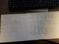
I have attached a couple of drawings of my project. My son and daughter in law just made me a grandpaw a few weeks ago. I have taken a 555 timer and configured it as a astable multivibrator. I am not to worried with the output frequency at this time and I will refine that later. I have taken the output of the 555 and ran it into the clock input of a cd4017 counter. I will be using the first five outputs of the 4017 to light up some LED arrays. So the first output will light the blue LEDs then the next output will light the green LEDs until the sixth output. The sixth output will be tied to the reset pin to restart the counter. The red, orange, and yellow LEDs will be wired like the top LED array and will draw 40 mA from the source. The blue LEDs will be wired like the middle array and will draw 100 mA from the source. The green LEDs will be wired like the bottom array and will draw 100 mA from the source. Each LED array will make one letter of my granddaughters name. If your still with me and understand my ramblings here is my question. I don't think the CD4017 outputs can source the current needed for the LEDs. I thought about using 5 2N2222 transistors to drive the LED arrays. I came upon a IC I have never used. The ULN 2804 has eight Darlington transistor arrays. I am looking at getting a 12VDC 1A wall wort to supply the project. Would I be better with the 5 2N2222 or the UNL2804? Thanks for all you help and I really enjoy this site.
Attachments
-
 2.7 MB Views: 24
 -
 2.9 MB Views: 21


