Need your help with 7 segment display using 4026 and NE555

Thread Starter

paradisevalo

Joined May 19, 2017
13
Hello,
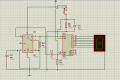
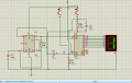
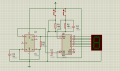
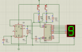
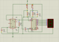
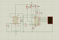
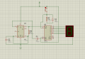
I have to make a circuit using IC4026 and 555 timer with 3 switches : one that pauses the counting, one that hides it and one that resets it. I'm having problems with the last two.
I have joined a picture of my circuit on proteus isis.
I'll be very grateful if you could help me.
 

Attachments

DickCappels

Joined Aug 21, 2008
10,140
Can you describe what your are seeing or not seeing?

At first glance you need to:
Put a resistor from U2 pin 15 to ground. Maybe 100k.
Ground the bottom of C4 and R2.
Connect U1 pin 7 to pin 6.

I don't know for sure what's going onwith U1 pin 4. This is usually tied to pin 8 which is in turn tied to V+ to allow the '555 to oscillate.

Where do you want the Master Reset pulse for U2 to come from?
 

Thread Starter

paradisevalo

Joined May 19, 2017
13
thank you for your help DickCappels !
when I connected U1 pin 4 to pin 7 the frequnecy became higher.
what I would like to do is add two switches to the one already existing ( one to reset the counting and another one to hide it but still counts until you let go of the button).
 

Attachments

dl324

Joined Mar 30, 2015
16,788
Yes it is. I'm sorry, did I post it in the wrong place ?
Not a big deal, happens frequently. I'll ask for the post to be moved.

For homework, we guide students to solutions. We also treat school projects as homework. Anything that you will receive a grade for.

Is pin 4 on the timer connected to VCC? Are pins 2 and 6 on the timer connected? I assume they are, but the connection dot usage is non-standard.
 

Thread Starter

paradisevalo

Joined May 19, 2017
13
I changed the circuit, now I can reset and pause the citcuit .
What I would like to do is hide the count when I push a button while it still goes on until I let go of the button then the display is on again.

Not a big deal, happens frequently. I'll ask for the post to be moved.

For homework, we guide students to solutions. We also treat school projects as homework. Anything that you will receive a grade for.

Is pin 4 on the timer connected to VCC? Are pins 2 and 6 on the timer connected? I assume they are, but the connection dot usage is non-standard.
Yes pin 4 is now connected to vcc and pin 2 and 6 are connected, as for what you said last I don't understand.
Thank you for your help.
 

Attachments

Thread Starter

paradisevalo

Joined May 19, 2017
13
Hello,

You are using a hysteretic 555 oscillator:
https://forum.allaboutcircuits.com/threads/555-hysteretic-oscillator.15342/
Remove the connection on the 555 between 6 and 7.

Bertus

PS I moved the thread to the homework forum
Thank yu for your help Bertus.
Does the CD4016 have a function that would enable you to do this?
At first I was using the circuit I joined and it did have this function but there was an error because vcc was connected to the ground.
 

Attachments

dl324

Joined Mar 30, 2015
16,788
At first I was using the circuit I joined and it did have this function but there was an error because vcc was connected to the ground.
I don't use Proteus. What do the colored squares mean? In particular, yellow.

Is the display enable function HIGH active or LOW active?
 

bertus

Joined Apr 5, 2008
22,266
Hello,

What is the switch at R1 supposed to do?
R1 is shorted, when you press the switch, you will short the powersupply.

Bertus
 

Thread Starter

paradisevalo

Joined May 19, 2017
13
Hello,

What is the switch at R1 supposed to do?
R1 is shorted, when you press the switch, you will short the powersupply.

Bertus
I shorted the power supply so that the pin 3 DEL in U2 is LOW to turn off the display output.
the switch is suposed to turn off the display while the counter still counts.
 

Thread Starter

paradisevalo

Joined May 19, 2017
13
Hello,

When you short the powersupply, everything will stop working.

Bertus
Yes you are right thank you.
I added a switch between pin 3 U2 and the supply.
So the display is on when the we push the switch and it is off when youlet go of the switch.
Is there any way without using logic gate NOT to have it display normaly and to turn off the display output when we push the button ?
 

Attachments

dl324

Joined Mar 30, 2015
16,788
Is there any way without using logic gate NOT to have it display normaly and to turn off the display output when we push the button ?
Put a pull-up resistor on EDI and use the switch to ground that input when you want the display disabled.

I understand that some simulators have crappy routing capabilities, but you need to work on drawing schematics that are easier to read. Unnecessary wire jogs/crossings, scenic routing, inconsistent usage of connection dots, etc, are all signs of a novice.

I used Multisim for a short while. It's smart routing feature created some really ugly schematics. With a bit of effort, I was able to force it to create neatly routed schematics.
 

Thread Starter

paradisevalo

Joined May 19, 2017
13
Put a pull-up resistor on EDI and use the switch to ground that input when you want the display disabled.

I understand that some simulators have crappy routing capabilities, but you need to work on drawing schematics that are easier to read. Unnecessary wire jogs/crossings, scenic routing, inconsistent usage of connection dots, etc, are all signs of a novice.

I used Multisim for a short while. It's smart routing feature created some really ugly schematics. With a bit of effort, I was able to force it to create neatly routed schematics.
Thank you very much dl324.
 
Top