Need to fake a thermocouple output from an MCU

Thread Starter

cjd7734

Joined Apr 30, 2018
7
I have a project in mind and I am looking for some advice
I need to rescale the value of a thermocouple as a passthrough device.

I have a machine that reads a thermocouple but is a closed source system. I want to make a board that reads the original thermocouple then outputs a signal to the original machine with data to rescale the thermocouple input.

K type thermocouple, the machine will not let it run higher than 300C I need to get to 375C
I can not change any part of the original machine, so I just want to use the original thermocouple and rescale the output.
I MCU and MAX31856 to read the original thermocouple.

the real question is how to fake the thermocouple output back to the machine from the MCU. I believe I need an adjustable mV output that is digitally controlled.

Thanks for the help
C
 

ebeowulf17

Joined Aug 12, 2014
3,307
I have a project in mind and I am looking for some advice
I need to rescale the value of a thermocouple as a passthrough device.

I have a machine that reads a thermocouple but is a closed source system. I want to make a board that reads the original thermocouple then outputs a signal to the original machine with data to rescale the thermocouple input.

K type thermocouple, the machine will not let it run higher than 300C I need to get to 375C
I can not change any part of the original machine, so I just want to use the original thermocouple and rescale the output.
I MCU and MAX31856 to read the original thermocouple.

the real question is how to fake the thermocouple output back to the machine from the MCU. I believe I need an adjustable mV output that is digitally controlled.

Thanks for the help
C
What kind of accuracy do you need when this thing is done? I ask because you've got numerous problems that are going to make it very hard to do a reasonable job of this:
  • Thermocouple readings are cold junction compensated, which means the ambient temperature where the thermocouple reading circuit is plays a role in the measurement. In order for your original device to get a useful reading, your new device will have to send a voltage corresponding to the difference between the target temperature signal and the ambient temp at the original device. If all the measuring circuits are in a temperature-stable environment with each other then these effects might be manageable.
  • Thermocouple outputs are non linear relative to the temperature they're representing. So, your new device will need a polynomial equation or a lookup table so that it can output a voltage that better represents the desired temperature signal. It won't be a simple, linear scaling situation.
  • Thermocouple voltages are super low. I seriously doubt you can find a DAC with the resolution you need at voltages that low, so even after all the issues above, you'll probably need a voltage divider and/or some op amps to scale the DAC output down to something that your original thermocouple output can read.
  • There are probably more issues I haven't thought of yet...
Anyway, I'm not saying it can't be done. Nearly anything is possible. Still, this seems like a difficult, roundabout way to accomplish something. There's gotta be a better way.

Then again, if resolution and accuracy in the signal to the original device don't matter, it would be relatively straightforward to read the thermocouple with your mcu and then send simple, loosely targeted high or low signals as needed. So it comes back to the question of resolution and accuracy.
 

Thread Starter

cjd7734

Joined Apr 30, 2018
7
Yep it is a roundabout way to solve the problem, but its the constraint I am operating with :)

resolution does not need to be super accurate .1 deg is probably fine
lookup table is probably fine
the rest of the system is temp controlled, so the cold junction issue is not a huge problem
I can also sample the existing system and scale from that.

A DAC might be the way to go, but I need to get it low enough voltage

Thank You
C
 

Dodgydave

Joined Jun 22, 2012
11,395
Your best option would be to alter the gain of the output, by 1.2, one way would be to use an AD595 chip or other instrument amplifier.

At 300C is 12.7mV,, 375C is 15.3mV, it's a very tight margin.

For higher temperatures you would have to reduce the input to the machine to fool it!
 

Thread Starter

cjd7734

Joined Apr 30, 2018
7
ah to be clear I need to read 375c and reduce it to the signal of 300c so I need a gain of .8 right ?

Thanks though it seems like we are moving in the right direction
 
One problem here is not knowing how thermocouples operate.

You need to place the unknown junctions on an isothermal block and know that temperature precisely. That block is usually around 25 C, room temperature. Having the TC tables in front of you, you need to look up the mV value for that temperature. Generally, the cold junction compensation has a limited range.

The other number is found by another lookup into the table for the 0C referenced value for the temperature desired.

the two number are added.subtracted (I forget which) to get the mV value that you need to present.

This means you need to know the temperature of the original place where the thermocouple connects.

There are polynomials and/or a look-up table.

==

Now another possible way to accomplish this and i have successfully done it. I needed to control the temperature of a substrate and not the oven temperature of a sample. The max difference was about 10 degrees. So oven was 200 and sample might be 188 C. The same phenomena the other way. I wanted the sample to be at 25C, so the chamber had to be at say 14C.

In this system the proportional band was 10 degrees. So. my +-100% was the current temperature +-10 degrees. I'd keep modifying that with PID and control sample temperature and not oven temperature.

An IEEE-488 bus RTD sensor was used for the surface temperature. The chamber had an IEEE-488 control too.
 

Thread Starter

cjd7734

Joined Apr 30, 2018
7
how about if I know the entire original thermocouple amp and connections are in a box that is kept at 100c ? and board I make would be in the same environment ?

I can easily get the table for the thermocouple

Thank You
C
 

ebeowulf17

Joined Aug 12, 2014
3,307
Yep it is a roundabout way to solve the problem, but its the constraint I am operating with :)
Fair enough. Bizarre constraints often lead to fun and interesting solutions. This should be an interesting project for you.
resolution does not need to be super accurate .1 deg is probably fine
Unless that decimal place is in the wrong place, I think you're in trouble. Achieving 0.1 degree accuracy with a thermocouple is very difficult, even at room temperature, with the junction in an ideal environment, and with only 1 amp involved. Accuracy drops as temperatures increase, and your scaling system is bound to introduce more error.

Unless you've got a traceable calibration point, like a platinum RTD, referenced near your 375 target temp, I think you be very lucky to land within several degrees of your target.

I'm sorry I'm on my way out the door and don't have time to dig up reference materials, so this is all off the top of my head, but I think you'll find that the accuracy you seek is unrealistic, or at least that it's in the realm of many thousands of dollars in cost! Hopefully that accuracy is a wish and not a requirement.

P.S. If you mean resolution, not accuracy, that's different. Resolution is easy - more bits in ADC and DAC - but it doesn't give you accuracy.
 

ebeowulf17

Joined Aug 12, 2014
3,307
Your best option would be to alter the gain of the output, by 1.2, one way would be to use an AD595 chip or other instrument amplifier.

At 300C is 12.7mV,, 375C is 15.3mV, it's a very tight margin.

For higher temperatures you would have to reduce the input to the machine to fool it!
Unless the junction temperatures are very tightly controlled, simply applying gain (or attenuation) won't give consistent results. If you want to make 375C read as 300C, but you've got a junction temp of 25C, then the thermocouple voltage will be the voltage corresponding to 350, and you'll need to scale it to 275, a factor of ~0.786. But if the junction is at 50C, then your TC voltage corresponds to 325C and you need to scale the output to 250C, a factor of ~0.769. And those examples are assuming both junction temps are exactly the same; it gets worse if they're different.

I don't think analog scaling will work unless junction temps are very tightly controlled, not just relative to each other, but in terms of absolute values.
 

ebeowulf17

Joined Aug 12, 2014
3,307
how about if I know the entire original thermocouple amp and connections are in a box that is kept at 100c ? and board I make would be in the same environment ?

I can easily get the table for the thermocouple

Thank You
C
Keeping both circuits at a very stable, known temperature is definitely a good idea and will provide your best chance of success. I don't think 100C is a good choice though, as that only adds to your measurement error. Most thermocouple amps, and their cold-junction-compensation circuits, are trimmed for best accuracy at room temperature, nominally 25C. The farther you get away from that, the less accurate your results will be.

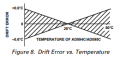
The image below is from the AD595 datasheet (datasheet here.) You can see that even 25C deviation causes 0.6C of extra potential error, so you can imagine that being 75C away from ideal will only create that much more error.
upload_2018-5-1_6-13-31.png
 

ebeowulf17

Joined Aug 12, 2014
3,307
Following up on my earlier comments about the difficulty in achieving tight accuracy tolerances, here's some more info from the AD595 datasheet:
upload_2018-5-1_6-30-40.png
Unless I've miscalculated (it is early, and I haven't had enough coffee yet!) this equals over +/-2.8 degrees C of gain error at 375C, plus +/-2.5C of stability error in the cold junction compensation at 100C, plus +/-1C initial calibration error, adding up to a total of +/-6.3C of error, just in the initial measurement circuit. That's the initial error of one circuit, then you've got the error of the TC itself, and you're adding two more circuits (your conversion circuit and the second TC measurement circuit.)

Of course, these are just specs from one readily available amp that I'm familiar with. You may be using equipment with significantly better specs, so it might not be this extreme, but just be aware that there are numerous sources of error even in an ideal thermocouple circuit, so make sure you have realistic expectations about the resulting accuracy of this system. Check the specs for the gear your working with (don't go off of my AD895 datasheet unless that happens to be what you're using) and add up all the error sources to see what kind of accuracy you can actually expect, and make sure it's acceptable for your application.
 

Thread Starter

cjd7734

Joined Apr 30, 2018
7
good timing I can accept wishful think on the accuracy, I started poking at this idea lat last night.

let's say I can accept the +/-6.3 error or more
The 100C environment unfortunately can not be worked around - which I can accept will impact the accuracy

I still need need to generate the output to feed into the original AMP
is the DAC to voltage divider driven by a MCU and a truth table a viable direction to go in ?

ignore the data acquisition phase for a moment, if you just wanted to build an arbitrary and adjustable thermocouple amp tester what would people do ?

Thank You
Calvin
 

ebeowulf17

Joined Aug 12, 2014
3,307
good timing I can accept wishful think on the accuracy, I started poking at this idea lat last night.

let's say I can accept the +/-6.3 error or more
The 100C environment unfortunately can not be worked around - which I can accept will impact the accuracy

I still need need to generate the output to feed into the original AMP
is the DAC to voltage divider driven by a MCU and a truth table a viable direction to go in ?

ignore the data acquisition phase for a moment, if you just wanted to build an arbitrary and adjustable thermocouple amp tester what would people do ?

Thank You
Calvin
It's a good question, and my analog chops aren't as good as I'd like, so I can't say for sure.

I'm inclined to think that a DAC and voltage divider would get the job done, but you can bet that proper, legitimate thermocouple test rigs have a better output stage than that. You could configure an op amp to buffer the output and do the scaling, but you need one with pretty good specs, and I doubt that even a rail to rail model can get you that close to 0V and stay accurate on a single supply. My money would be on a dual supply op amp output stage (of course, the negative side of the supply won't need much current, so I imagine you could use a charge pump IC voltage inverter for the negative supply if you don't already have a dual supply going.)

Hopefully some of the experts here can help a little more with how to design a good output stage in the low millivolt range. I have vague ideas, but I don't have the experience to back them up. Sorry.
 

Hymie

Joined Mar 30, 2018
1,347
I know that messing with thermocouples can easily screw up their response – but could you not simply use a buffer op-amp with a resistive voltage divider at the output?

A K type thermocouple has a voltage of 0V at 0C and around 15.3mV at 375C (and 12.2mV at 300C).

Noise pick-up could significantly reduced by capacitor filtering with a time constant of the order of seconds – with the likely thermal mass involved (slow temperature change rate of the system).

Admittedly all temperatures readings between 0 – 375C would be increased by a similar factor – but would that be an issue with what you are proposing to do?
 

Thread Starter

cjd7734

Joined Apr 30, 2018
7
so I just need to hit and stay around a target temp (375c) which the controller needs to see as 300c, so the middle range when it is heating up accuracy is not really an issue at all

C
 

ebp

Joined Feb 8, 2018
2,332
Take the signal from the thermocouple directly to a unity gain amplifier (needs to be low offset voltage type). Don't do cold junction compensation. Add an offset voltage equal to a delta of 75°C from the thermocouple (actually subtract it), which will require a precision voltage reference and good resistors (0.1% 25 ppm/°C SMD types are quite cheap and probably satisfactory). Feed output to input of machine. Tweaking the offset is sufficient for a single point calibration, if necessary.

You don't want to do cold junction compensation since the machine is already doing it by essentially subtracting the voltage produced by the junction at the "cold" end (keeping in mind the polarity of that junction). You are simply telling it a -75°C lie. Because the change in working temperature of the machine may change its dynamics, this may have some effect on PID control optimization.

Unless you know for sure the machine won't detonate at 375°C, hide behind something big and solid. Perhaps notify next of kin of your plans.
 

ebp

Joined Feb 8, 2018
2,332
I may be away from AAC for a few days, so hopefully others will make suggestions of suitable parts. Any op amp with low input offset voltage and rail-to-rail input and output should be OK. It will likely be necessary to add a rather low-value pull-down resistor to the amp output to be sure it performs well very close to the rail.
 

Hymie

Joined Mar 30, 2018
1,347
Can you point me a unity gain amplifier IC as an example to use for this ?
Here is a circuit that might do what you want – using 308 low drift instrument op-amps.

The thermocouple input is fed into U1, configured as a unity gain buffer, U2 provides off-set adjustment via VR1 and a small amount of gain.

The capacitance values at the non-inverting input to U2 and at the circuit output can be any value to minimise pick-up noise.

Output attenuation is provided by adjustment of VR2.

The 308 op-amp will operate from +/-2V to +/-18V rails, but since you are only interested in low voltages I recommend maximum supply rails of +/-5V for your circuit.

To set up the circuit, with the thermocouple in iced water, adjust VR1 such that the output of U2 is at 0V, then with the thermocouple at 375C, adjust VR2 such that the instrument thinks it is reading 300C.

You might consider using 10 turn pots for VR1 & VR2 to allow for very fine adjustments.
 

Attachments

ebeowulf17

Joined Aug 12, 2014
3,307
Top