Need simple voltage regulation on low-side relay drive circuit

AnalogKid

Joined Aug 1, 2013
12,174
Post #10:
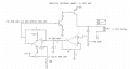
Here is the idea:

V2 represents the micro output.
R2, Q1 and R3 are the current limiter. Adjust R3 to adjust the target current.

As you can see, it does not exactly regulate the current, but it might be sufficient to keep it within the operating range.
Agree.

I like an all-discrete, analog approach <duh>. In the circuit in #8, the 317's stability as a current regulator is scary-good. The problem is the headroom requirement of at least 2 V. That's nothing in the 12 V case, but means a 6 V relay is seeing only 4 V in the low voltage case, probably not enough for reliable operation.

ak
 
Last edited:

dcbingaman

Joined Jun 30, 2021
1,065
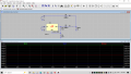
The following model with negative feedback could work:

1697318201432.png
Everything here is normalized to 1. 1V/A on the sense resistor. 9V/A out of the first op-amp stage. The time constant on the filtering is 1 second due to normalization. The second stage -9V/A+11V/A= 2V/A. And the negative feedback is -1V per amp but it is multiplied by the PNP transistor gain, thus we get a fairly high amount of overall amplification of the PNP transistor. The circuit may oscillate, thus it will need fine tuning.

'Reasonable parts need to replace the normalized parts then it can be examined by a spice program.
 

AnalogKid

Joined Aug 1, 2013
12,174
There are no reference designators, so any real discussion is very difficult. The top-most transistor has no impedance across the base-emitter junction, so it will not turn off quickly or reliably. There is nothing in the circuit that senses the current through the relay coil, so it is not clear what the circuit does to solve the problem. All I see is a saturated switch putting 12 V on a relay coil no matter what the rest of the circuit does, but the (?) opamp output is saturated high and there is no base current limiting for the other transistor, so it burns up and the relay turns off.

Which nodes would connect to a negative feedback circuit?

And - what is the purpose of the diode?

ak
 
Last edited:

LowQCab

Joined Nov 6, 2012
5,101
You only need 4-Parts,
A LDO-Voltage-Regulator,
2-Stabilization-Capacitors, ( possibly only one, if the Power-Supply already has a Capacitor nearby ).
and a Spike-Suppression-Diode across the Relay-Coil, ( which is needed in any case ).

The Voltage-Regulator can be set-up as a Current-Regulator just as easily.

There's at least ~50 LDO-Regulator part-numbers to choose from that will all get the job done.

My preference would be to install a single Op-Amp to drive the Gate of the Switching-FET,
which has been set up in a Current-Regulator-Feedback configuration.

It may be possible to use the MC to do the Current-Regulation with only the addition of one Resistor.
.
.
.
 

k1ng 1337

Joined Sep 11, 2020
1,038
An easy solution would be to OR the supplies with Schottky diodes. For the 12V supply, use LM317 voltage regulator to drop the extra voltage. You have the headroom for the IC and it meets your power requirements with a heatsink. It might be a good idea to only connect one supply at a time to avoid a fault condition.
 

MisterBill2

Joined Jan 23, 2018
27,717
OK, back from post#1. The relay is controlled by a low side N-Channel MOSFET . So current limiting on the supply side would be the answer.
What we do not know yet is if the system is battery powered or if efficiency matters a lot. The requirement so far is a minimum parts count, which would seem to suggest a single transistor current limiter that has a very small voltage drop below the lower relay current. We also have no hint as to how long the repay will be energized, or how frequently it will be operated.
A drain resistor for the mosfet switch, to take it out of saturation when the current is greater is one option not yet considered. That resistor can be shunted by a capacitor to allow for the relay pull-in current to be greater. That is one possibility that has not yet been discussed.
 

Ian0

Joined Aug 7, 2020
13,158
What's not so clear is whether it has to cope with 6V and 12V, or with 6V, 12V and every possible voltage between, because he initially mentions a comparator set a 8V.
 

AnalogKid

Joined Aug 1, 2013
12,174
I think the 8 V comparator says everything within the range. It could be that it really is only 6 or 12, and he is mentioning an 8 v comparator as a conceptual approach. But there really isn't much difference. A 2-transistor constant current circuit has very low headroom, and puts a 3.9 ohm resistor in series with the coil in the 6 V case, which should not be a problem. A 6 V relay certainly will activate on 5.4 V.

a
k
 

Danko

Joined Nov 22, 2017
2,186
Need simple voltage regulation on low-side relay drive circuit
I have a working relay drive circuit using a low-side N-Channel MOSFET driven by a microcontroller. The relay coil is 6V, and everything there works. However, I want the same coil to work with a 12-volt supply as well, without burning the coil.
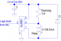
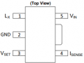
Circuit is simplest,
Switching mode, therefore up to 97% efficiency,
Does not need heatsink or hot resistor,
Price of driver AL8861WT-7 is $0.68.

1697386700611.png1697386837762.png
 
Last edited:

k1ng 1337

Joined Sep 11, 2020
1,038
Post #1 is pretty clear about there being only one power source input, which is why he needs a circuit that compensates automatically.

ak
I didn't get that impression at all. He said his circuit works fine with 6V and wants to add 12V capability. If this is the case, all we need to do is get rid of 6V as my understanding of relay coils are essentially a fixed resistance actuated for a short time (high current pulse). Also, the coil is being driven periodically and the diodes provide protection against reverse currents. A 555 timer could be added to lock out each switch so only one can be active. Are you suggesting the supposed downstream circuitry makes my suggestion untenable? I don't know much about relays..

I would opt for two inputs as my circuit is a modular addition that costs a few bucks. Why go through the trouble to retrofit a working circuit to accept 6 or 12V on the same input?
 
Last edited:

Thread Starter

memotronics

Joined Apr 9, 2021
10
The supply is either 6VDC (5 to 8) or 12VDC (11 to 14), this is for an automotive application that should also work reliably in 6V vehicles, i.e. your pre-1950s cars. I also have VERY limited space on the PCB, and to make matters worse, the total quiescent current has to be in the uA range. Last but not least, I can't have a flyback diode across the coil because of the effect this has on the relay contacts (I read some long-ass article about that which said that, to prolong the contact life, a zener should be placed across the MOSFET drain/source, this was news to me as well). I was really starting to like the AL8861 idea. There's a different issue I'm having (will post that shortly), which may mean that we need to have 2 different circuits anyway (one for 6V, one for 12V), in that case we'll just use different relays and at least this issue may then be moot. I'm just glad that it's not something super-simple that I overlooked, and I RELALY appreciate the help.
 

MisterBill2

Joined Jan 23, 2018
27,717
One option not mentioned yet is one of the PTC protective devices that would limit the relay current before it could overheat.
And I still think that a resistor between the source and negative, below the relay, could raise the source voltage when there was more current, which would reduce the conduction of the mosfet. It would be a negative feedback arrangement.And it would add only one small part
 

AnalogKid

Joined Aug 1, 2013
12,174
One option not mentioned yet is one of the PTC protective devices that would limit the relay current before it could overheat.
Those tend to change quickly to a high impedance, as a sorta solid state fuse. They are not good for steady-state current limiting.

And I still think that a resistor between the source and negative, below the relay, could raise the source voltage when there was more current, which would reduce the conduction of the mosfet. It would be a negative feedback arrangement.And it would add only one small part
The operating point of the circuit would have to sit on the curvy part of the FETs transconductance curve, something that is not consistent from part to part and varies significantly with temperature.

ak
 

AnalogKid

Joined Aug 1, 2013
12,174
An analog current limiter of just about any flavor is simple, cheap, and has no EMI. But that 1 W has to go somewhere, and that can't be a 2N7000 or 2N3904. Because a relay's holding current is less than its actuating current, there is a capacitor trick that would reduce the steady-state dissipation by about 33%. Bad news is the capacitor size.

ak
 

BobTPH

Joined Jun 5, 2013
11,569
If you are producing multiples of this for different cars, the obvious solution is to use a 6V or 12V coil relay when you build each one. I am sure you can find a family of relays that have the same footprint with different coil voltages.
 
Top