need simple counter for enabling solid state relay

Thread Starter

Carolsboy

Joined Feb 7, 2018
27
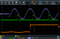
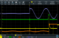
I am working on my LED Driver Inrush test fixture and have things working pretty smooth. I used an H11AA1 optoisolator with a diode to switch on the positive cycle when a momentary pushbutton switch is depressed. The optoisolator when it turns on pulls the base of an NPN transistor low and allows a ramp generator to generate an 8mS ramp that is fed to a comparator that allows me to output a positive 5V pulse that is fed to a transistor latch circuit that turns on a random crossing SSR relay that enables my driver at the peak positive voltage. The only issue is that I can still trigger the latch circuit if the button is pressed during the rise time of the positive cycle, which delays the start of the ramp and fires the SSR late. I believe that if I add a flip flop or some kind of counter between the comparator and the latching transistors that puts out a positive 5V pulse after the second positive output from the comparator, it will be timed perfectly every time the switch is pressed. I was looking at using a D type flip flop with /Q tied to D and the comparator output tied to the clock input, but the output will go high on the first clock. I want a circuit that will count 2 and then go high on the rising edge of the second pulse. I am guessing I may need to reset the circuit when the momentary button is released. I should be able to figure this out, but just want to get ideas quickly to consider.

Any ideas???? Thank you in advance.
 

Thread Starter

Carolsboy

Joined Feb 7, 2018
27
I am guessing I can cascade both D-type flip flops (SN74HC74) with /Q tied to D on each flip flop and tie the reset pins together with a pull up and tie that to a NC reset switch block that I can add to my industrial momentary NO switches that I am using to fire the optoisolator and enable the latch circuit.
 

Attachments

Thread Starter

Carolsboy

Joined Feb 7, 2018
27
Any schematic?

ak
Here is my circuit... without the counter circuit between the comparator and latch circuit.... it stills shows a contactor as the output load, but I plan on switching to (3) SSR's as the contactor contact bounce was excessive during the first 10mS after switching and affected the inrush waveform on the scope (I need a SSR for L1 (277VAC), L2 (277VAC) and 120VAC).
 

Attachments

Thread Starter

Carolsboy

Joined Feb 7, 2018
27
So here are two oscilloscope screenshots one showing the contactor latch occurring exactly at peak voltage, the second shows when the button is pressed after the positive cycle has already started and then the latched output occurs after the peak... the idea is that if I latch after the second positive output from the comparator, it will always be timed correctly. The output on channel 3 is the contactor output contacts with 24VDC to see the switch bounce, which is excessive and why I am changing to SSR's.
 

Attachments

AnalogKid

Joined Aug 1, 2013
11,043
I think Q2 is upside down.

I was headed toward a single input ff, but Wally beat me to it. It moves S1 to the secondary side of the opto.

Why not use the other half of the 6482 as the comparator?

ak
 
Last edited:

Thread Starter

Carolsboy

Joined Feb 7, 2018
27
I think Q2 is upside down.

I was headed toward a single input ff, but Wally beat me to it. It moves S1 to the secondary side of the opto.

Why not use the other half of the 6482 as the comparator?

ak
Yes, Q2 is drawn incorrectly... I didn't even notice it, but the positive must go to the emitter on a PNP as shown on Q4, my circuit is breadboarded correctly, thanks :)
I guess I could have used the opamp for the comparator and save board space on the layout when I get it working optimally. I see your point on the switch... why have 120 on it when I could connect it between ground and the emitter of the photo transistor on the opto. The only reason I did it this way is the current limiting resistor won't get hot if it is only powered when the test is being made. I picked a 1W resistor and I believe the power is approx. 0.34W based on half wave rms value of 88.84V (Vpk/2), so I should be OK. I will have to install a main on/off switch when I get to the final assembly of the fixture itself. Thanks for the help :)
 
Last edited:

Thread Starter

Carolsboy

Joined Feb 7, 2018
27
Here is the output of my modified circuit using the cascaded flip flops showing the Q1 output always triggering at 90 degrees even when the test switch is pressed after the positive cycle has started... just what I wanted... a repeatable inrush waveform on my scope :) first pulse starting after zero degrees.PNG
 
Last edited:

Thread Starter

Carolsboy

Joined Feb 7, 2018
27
I haven't updated it yet, but I put the <counter_2 bit d type.jpg> circuit I attached above into the schematic where the input to the clock comes from the comparator output and the output of the second flip flop (Q1) goes to the anode of the diode of D2. I connected the set pins of both flip flops to make them inactive and connected the reset pins together with a pull down and a NC switch block on my test switch is used to reset the flip flops when the switch is not being pressed. I moved the input momentary switch from the 120V input and connected the input directly and put the NO switch between the optoisolator emitter and ground.

I am likely going to add more optoisolators and let them do the actual latch, flip flop reset and input opto enable and get back to one switch block on my switch.
 
Last edited:

Thread Starter

Carolsboy

Joined Feb 7, 2018
27
Decided to make another change... since the 120VAC phase angle is different from all three phases of the 277VAC, and since the 120VAC is likely one of 3 different phases made from a 208 transformer, I am going to make 3 separate input optoisolator circuits for the 120VAC, 277VAC and 480VAC input voltages coming into the test fixture and use three more optoisolators to connect the appropriate phototransistor emitter to ground depending on the selected voltage of the driver. This will ensure the timing circuit ramp generator is triggered by the actual voltage that will be feeding the driver no matter where the 120VAC or 277VAC plugs are connected. Once I set up the timing. I can take the fixture into any test lab and be sure the timing is adjusted properly.
 
Top