Need ideas to 3d map a boat.

Thread Starter

strantor

Joined Oct 3, 2010
6,782
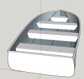
I got a 14ft jon boat that I need to make a dimensionally accurate 3D model of. It's an old school "skiff?" style with lots of curves. I wish it were The newer style that's more angular.

The extent of my 3D modelling has been designing things that didn't exist yet. This will be my first try at recreating something that already exists. So far my only bright idea is to tape a network of strings inside so that the strings all come together with each other as triangles. Measure the triangles, enter dimensions into CAD, and then use some curve functions to tie it all together. That just seems very labor intensive and easy to get it wrong.

Any better ideas?
 

Attachments

wayneh

Joined Sep 9, 2010
17,496
I’ve never used one, but there is a laser scanning tool that can make a digital model of a 3D object. No idea if one could be found for scanning something as large as a boat.
 

wayneh

Joined Sep 9, 2010
17,496
Yeah I'm on a "free boat" sort of budget here. I should have mentioned that. Thanks though.
I think if it was me, I'd park it by a wall or other reference and measure everything relative to that reference. Take as many measurements as needed to achieve the precision you need. Why in the world do you need to model your boat?
 

Thread Starter

strantor

Joined Oct 3, 2010
6,782
I think if it was me, I'd park it by a wall or other reference and measure everything relative to that reference. Take as many measurements as needed to achieve the precision you need. Why in the world do you need to model your boat?
I'm designing some rather radical bolt-on and weld-on modifications and need to try them on for size before building them. Mainly, installing a ford focus engine in it.
 

Alec_t

Joined Sep 17, 2013
14,280
If a laser scanner is beyond your budget then I think you'll need to set up 3 fixed reference points, well spaced in 3 dimensions, then measure accurately the distances of numerous strategic locations on the boat from each of the 3 reference points. There must be an app for doing the sums to get the co-ordinates of the locations from the measured distances :).
 

shortbus

Joined Sep 30, 2009
10,045
I don't do CAD, putting that out up front, but had a beginning course when working years ago. But looking at your photo taken from the stern it looks to me like you have all that's necessary. Without a scanner or out lay of money.

1. Stretch a string or wire, from the center of the bow at the point, to the center of the transom. This becomes your 'data line' (DL).

2. Then measure from the DL to the outside of the hull at each one of the braces coming from the set to the hull. Those measurements become your "X" coordinates in the drawing.

3. Measure the distances between the transom and the first brace, and between each brace to the bow point. Those become your "Y" coordinates.

Now in the program we used there was a part in it that allowed you to draw a 'fair curve or radius' between two points. Fair curve is a term used in boat building and many other things like furniture and musical instrument building. Just means basically that the curve or radius fits between two points with no "hiccups". Before CAD it was done using a French curve in drafting or a stiff but flexible piece of material like a thin piece of wood to connect the points.
 

panic mode

Joined Oct 10, 2011
2,715
agreed, place it into a box (can be just stretched strings around it) and measure points with tape. The more points you create, the more accurate model. Also this is symmetrical so one can simply mirror points. this means you can go to hardware store, get piece of Styrofoam, cut it and place in the middle of the boat (like mirror between left and right side) then measure from there.
 

BR-549

Joined Sep 22, 2013
4,928
Try to contact manufacturer. Do not talk to salesman. Ask for an engineer and ask for a print. Assure him it's a private one time modification.
 

atferrari

Joined Jan 6, 2004
4,764
Hola strantor,

Google "bonjean curves"; it could spark ideas. They are used by naval architects not by crew.

My brother, an incredibly good modelist, used to define the sections, materialized with the model's frames and then build the hull.

It seems a nice problem to be solved with CAD software.

Edit/ To add few pictures not to derail your thread.

03.JPG

Friederich Ihn.jpg

Not only ships.

Krupp-5.jpg

Nowadays, after smoking heavily, he is rather limited but still able to produce incredible things.

IMG-20170906-WA0001.jpg


The young guy in action. The most sophisticated tool he ever used was a faithful cutter. Believe me.

05.jpg

/Edit
 
Last edited:

wayneh

Joined Sep 9, 2010
17,496
Try to contact manufacturer. Do not talk to salesman. Ask for an engineer and ask for a print. Assure him it's a private one time modification.
I have had some experience in the boat manufacturing industry and not once have I seen an engineer employed there. All I saw was guys named Bubba that could spray fiberglass into a mold. The sales guy ran the company and was the hull designer and 'engineer'. There are surely some engineers in the industry somewhere but I think it would be very difficult to get drawings for a small boat, even if you could find such a person.

Personally, I think I'd try to measure the critical dimensions and start making a prototype for fitting. That process would identify where the critical dimensions actually are. I wouldn't bother modeling the entire boat.
 

Thread Starter

strantor

Joined Oct 3, 2010
6,782
This boat is from the 70s. I doubt Lowe have the info I need. If anything they probably have cutout dimensions which don't help me and they probably wouldn't give them out anyway.

I'm well on my way to modeling this thing. I've been working on it all day. Starting to look like an aluminum boat.
 

Attachments

Thread Starter

strantor

Joined Oct 3, 2010
6,782
OK I'm done. I just took triangulation measurements all over the thing. Unfortunately there weren't two good reference points from which everything could be measured.
This took me ALL DAY. 7AM to 5:30PM measuring and modelling. I totally underestimated how complex the shape of a simple boat is.
It isn't gnat's ass accurate, but hell, it's an aluminum boat. If I need the boat and the model to agree, I can beat the boat with a BFH until it matches the model.
 

Attachments

xox

Joined Sep 8, 2017
838
OK I'm done. I just took triangulation measurements all over the thing. Unfortunately there weren't two good reference points from which everything could be measured.
This took me ALL DAY. 7AM to 5:30PM measuring and modelling. I totally underestimated how complex the shape of a simple boat is.
It isn't gnat's ass accurate, but hell, it's an aluminum boat. If I need the boat and the model to agree, I can beat the boat with a BFH until it matches the model.
Not bad for a day's work. Good luck on the project!
 

MaxHeadRoom

Joined Jul 18, 2013
28,619
Top