Test per post #73 (Q3a and Q7a installed)
Upon power up, millivolt reading at speaker terminals was -62.0 mV and dropping.
Voltage across R17a = starts at +.53 volts and is climbing
Voltage across R18a = starts at -.53 volts and climbing
After a few minutes, R17a is at +.694 volts and R18a is at -.712 volts
After 10 full minutes:
Voltage across R17a = +.677 volts and pretty steady
Voltage across R18a = -.694 volts and pretty steady
millivolt reading at speaker terminals pretty steady at -0.2 mV (-.0002 V)
main heat sink is mildly warm on channel A side only. Channel B side is still cold.
Q1a and Q2a are equally hot.
Signs are good.
The biasing is high that is why Q1 and 2 are hot.
You can drive a 8Ω speaker at 1/4 the volume now.
Just to check sound is OK. Never increase the volume and never use 4Ω speakers for this test.
Can you confirm that Ch B's Q1b & Q2b are around the same temperature as ch A's Q1 &Q2 when Amp is idling without sound.
If you up to it compare the same voltages you just did. It will confirm if the biasing needs to be reduced or not.
If the voltages are identical between ch A & B and if you can hear good sound then you are ready to solder all the Power Transistors and drive the bugger all the way.
Happy Sounding.
Tonight, I'll insert the fuse for channel B, and idle the amp. I'll report back with voltages and temperatures. Thank you very much for doing all the work, R!f@@ !
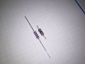
I'll have to switch out R17a and R18a for 2W resistors.
Here's picture of the old blown resistor, and the 1W resisitor that I have in right now. Looks the same, but thanks to Mr Chips, my 1W is not the same as the 2W.
With both fuses installed, warmed up for 10 or 15 minutes. Channel A speaker terminals -2.9 mV. Channel B speaker terminals -1.1 mV. Gain for both channels at 0. Voltages at R17 and R18 were similar (do not have the actual data handy).
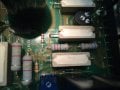
At that point, I replaced the two 1W resisters with new 2W resistors, 22 ohm (edited) 2%. Also proceeded to install the rest of the power transisters. Everything seemed functional. Bridged the channels and still good.
This is an old, old amp. Not sure how much longer it has...but I have certainly enjoyed learning on it. You have been very patient, and donated plenty of time. I thank you very much.
Good to hear you fixed it but replacing 22Ω with 20Ω will raise Iq and dissipate more power in the drivers. from temp measurements you can see that. In the long run it will be disastrous.
You might just blow it when the temp rises too much. If you do not blast it for extended duration they might hold
 Facebook
 Google
 GitHub
 Linkedin
 1.5 MB Views: 31