Facebook
 Google
 GitHub
 Linkedin
Hi!
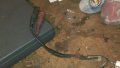
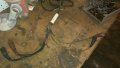
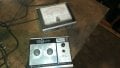
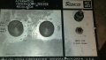
I fried my old Snap-On ammeter. It has 0 to 10 amp and 0 to 100 amp circuits and I connected the 0 to 10 amp leads in series with a 6 volt circuit on an old tractor that, it turns out, had a dead short in it. The result was smoke from a tubular container in the leads. When I opened the tube, which contains the leads for both ranges, I found the 100 amp leads connected to a rectangular metal plate in what appears to be a shunt type setup, in that the leads from the plate to the clips are a heavy gauge and the leads from the plate to the meter are a much lighter gauge. Both the lead to the clip and the lead to the meter for each side of the circuit are soldered together at each end of the plate. That part seems to be intact. there is a piece of insulation material, almost like a rectangle of circuit board, slightly larger than the metal plate, that separates the 0 to 100 amp and the 0 to 10 amp wiring.
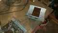
The smoke seems to have come from the 0 to 10 amp range wiring. The leads are the same configuration with a heavier lead going to the clip than to the meter. the lead to a clip and the lead to the meter for both sides are soldered together and to a piece heavy solid wire. the heavy solid wire connected to both pairs of leads have the remnants of "something" at the end of the heavy solid wire opposite the end connected to the leads that obviously was completely destroyed. That's what I need help with. I expect that the part that was destroyed is a shunt resistor, but I have no idea how to determine its value or what wattage I should use.
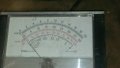
The meter deflects appropriately when used to test voltage, so I don't think it was damaged. I have also traced both the 0 to 10 amp and the 0 to 100 amp circuit paths all the way from the wire at the tube through the rotary switch, the components on the board, the meter, and back the the tube on the other side of the circuit and there are no failed components.
If someone could help me out I sure would appreciate it. I know just enough to be dangerous!
Thanks!
I fried my old Snap-On ammeter. It has 0 to 10 amp and 0 to 100 amp circuits and I connected the 0 to 10 amp leads in series with a 6 volt circuit on an old tractor that, it turns out, had a dead short in it. The result was smoke from a tubular container in the leads. When I opened the tube, which contains the leads for both ranges, I found the 100 amp leads connected to a rectangular metal plate in what appears to be a shunt type setup, in that the leads from the plate to the clips are a heavy gauge and the leads from the plate to the meter are a much lighter gauge. Both the lead to the clip and the lead to the meter for each side of the circuit are soldered together at each end of the plate. That part seems to be intact. there is a piece of insulation material, almost like a rectangle of circuit board, slightly larger than the metal plate, that separates the 0 to 100 amp and the 0 to 10 amp wiring.
The smoke seems to have come from the 0 to 10 amp range wiring. The leads are the same configuration with a heavier lead going to the clip than to the meter. the lead to a clip and the lead to the meter for both sides are soldered together and to a piece heavy solid wire. the heavy solid wire connected to both pairs of leads have the remnants of "something" at the end of the heavy solid wire opposite the end connected to the leads that obviously was completely destroyed. That's what I need help with. I expect that the part that was destroyed is a shunt resistor, but I have no idea how to determine its value or what wattage I should use.
The meter deflects appropriately when used to test voltage, so I don't think it was damaged. I have also traced both the 0 to 10 amp and the 0 to 100 amp circuit paths all the way from the wire at the tube through the rotary switch, the components on the board, the meter, and back the the tube on the other side of the circuit and there are no failed components.
If someone could help me out I sure would appreciate it. I know just enough to be dangerous!
Thanks!