Facebook
 Google
 GitHub
 Linkedin
I have a motorcycle with a gas gauge. The sending unit for that gauge reads 10 ohms when the tank is full and 215 ohms when the tank is empty. OK so far.
I want to add a second gauge (2 total gauges). The second gauge requires a sending unit that reads 10 ohms when full but only 70 ohms when empty.
So, if I simply parallel the two gauges, the additional one will read empty long before the tank gets empty (70 ohms vs 215 ohms). Also, I suspect that paralleling two gauges will make the original gauge read wrong, too. That really complicates the problem.
I can't install an additional sending unit in a motorcycle tank. No way to do that.
I measured with the second gauge since it's on my workbench. Here's what I got. I connected the 12 volt pin to a 12 volt gel cell battery that measured 12.8 volts. The sensor pin was connected to a 10-turn 100 ohm pot. The other end of the pot was connected to the battery's negative terminal. I then measured the voltage across the resistor (with a DVM).
Voltage across the resistor Voltage across the gauge
10 ohms - 1.06 v = 106 ma 11.74 v
20 ohms - 1.82v = 91 ma 10.98 v
30 ohms - 2.36 v = 78.6 ma 10.44 v
40 ohms - 2.80 v = 70 ma 10.0 v
50 ohms - 3.12 v = 62 9.68 v
60 ohms - 3.41 v = 56.8 ma 9.39 v
70 ohms - 3.63 v = 51.7 ma 9.17 v
You can see it's nonlinear, but not too far off.
I haven't measured the motorcycle's gauge. I'm going to try that ASAP. Then Ill know the ratio between the two gauges.
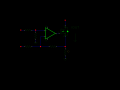
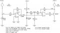
Attached is an op-amp circuit that I think will work. The op-amp will input the voltage across Gas Gauge 1 and amplify it to the correct level for Gas gauge 2. Right now I don't know exactly what voltage will be across Gas Gauge 1 since I havent measured it yet, but I do know the voltage required for Gas Gauge 2 is approximately 9.2 to 11.74 volts based on V1 being 12.8 volts. Of course V1 will be higher when the motorcycle is running, but I think the ratio will be close enough. After all, its just a gas gauge. Anybody ever seen an accurate gas gauge?
I doubt that the two gauges need the same voltage so that would mean I need a non-linear differential amplifier(?) since both gauges need 10 ohms to read full, but they need totally different resistances to read empty (215 vs 70 ohms).
Also, the op-amp will need to be able to source 100 ma or so.
Anyone know how to do that?
Jack
I want to add a second gauge (2 total gauges). The second gauge requires a sending unit that reads 10 ohms when full but only 70 ohms when empty.
So, if I simply parallel the two gauges, the additional one will read empty long before the tank gets empty (70 ohms vs 215 ohms). Also, I suspect that paralleling two gauges will make the original gauge read wrong, too. That really complicates the problem.
I can't install an additional sending unit in a motorcycle tank. No way to do that.
I measured with the second gauge since it's on my workbench. Here's what I got. I connected the 12 volt pin to a 12 volt gel cell battery that measured 12.8 volts. The sensor pin was connected to a 10-turn 100 ohm pot. The other end of the pot was connected to the battery's negative terminal. I then measured the voltage across the resistor (with a DVM).
Voltage across the resistor Voltage across the gauge
10 ohms - 1.06 v = 106 ma 11.74 v
20 ohms - 1.82v = 91 ma 10.98 v
30 ohms - 2.36 v = 78.6 ma 10.44 v
40 ohms - 2.80 v = 70 ma 10.0 v
50 ohms - 3.12 v = 62 9.68 v
60 ohms - 3.41 v = 56.8 ma 9.39 v
70 ohms - 3.63 v = 51.7 ma 9.17 v
You can see it's nonlinear, but not too far off.
I haven't measured the motorcycle's gauge. I'm going to try that ASAP. Then Ill know the ratio between the two gauges.
Attached is an op-amp circuit that I think will work. The op-amp will input the voltage across Gas Gauge 1 and amplify it to the correct level for Gas gauge 2. Right now I don't know exactly what voltage will be across Gas Gauge 1 since I havent measured it yet, but I do know the voltage required for Gas Gauge 2 is approximately 9.2 to 11.74 volts based on V1 being 12.8 volts. Of course V1 will be higher when the motorcycle is running, but I think the ratio will be close enough. After all, its just a gas gauge. Anybody ever seen an accurate gas gauge?
I doubt that the two gauges need the same voltage so that would mean I need a non-linear differential amplifier(?) since both gauges need 10 ohms to read full, but they need totally different resistances to read empty (215 vs 70 ohms).
Also, the op-amp will need to be able to source 100 ma or so.
Anyone know how to do that?
Jack
Attachments
-
 16.6 KB Views: 65
")