Need Help with multiple 555's or 556's

Thread Starter

iONic

Joined Nov 16, 2007
1,662
What I'm trying to do here is to press one momentary switch and set off a series of pulse event for varying lengths of time. For example I want to run a square wave pulse with output of 5V for aprox. 10 minutes, then got to a second square wave with a output voltage of 10V for 15 minutes...etc.

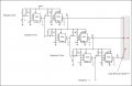
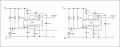
I thought that by using a 556, the first timer to set the first duration and the second timer to provide the pulsed voltage could do this for me.
The attached schematic shows two 556's that do just this. The brain fart I am having is how to tie the two 556's together so that when the first one is complete the second one will begin, then end and either continue to the the third, fourth, and recycle to the first once again.

Thanks for the input.
 

Attachments

Wendy

Joined Mar 24, 2008
23,415
The second timer needs to be capacitively coupled AND have a pull up resistor on the trigger, similar to what you have for the first timer.
 

Wendy

Joined Mar 24, 2008
23,415
If I read your schematic correctly (that format is hard to read) you aren't connected to the trigger on the second timer. The trigger also has to have a pull up resistor.

**************************

Here's my redraw of the circuit...


Just repeat the second part ad infinitium.

Since the trigger responds to the negative going edge you don't need invertors.
 
Last edited:

Thread Starter

iONic

Joined Nov 16, 2007
1,662
Bill,
Not sure I follow exactly. The circuit I drew was a redraw from a circuit at the following link. http://home.cogeco.ca/~rpaisley4/LM555.html#6 (Circuit #1). I see how to trigger the second 556 with the previous one and I'm hoping that this is all I need for my needs. Thus I redrew you circuit for multiple operation.
Please let me know if I did this right!
 

Attachments

Wendy

Joined Mar 24, 2008
23,415
Without a gate you can not merge outputs of a 555. They form a low conduction path to either supply rail, so if one is high and another low you have a short.

Maye I'm missing what you are trying to do? I thought you wanted to sequence each timer from the one before it, to form a moving pulse. Correct?


If this isn't what you want you might try defining what you're trying to do a little better.
 

Wendy

Joined Mar 24, 2008
23,415
It just occured to me what you might be trying to do. The question is (assuming this is correct) do you want to control each side of the square wave independently?


Wendy

Joined Mar 24, 2008
23,415
OK, I used a diode gate because it is easily expanded.


More like what you're after? You can increase the drive on the output by using a transistor or another 555 wired as a Schmitt Trigger.
 

Wendy

Joined Mar 24, 2008
23,415
OK, the dead time is going to have to be controlled somehow, I'm assuming with another 555. So each section will have 3 555 timers, from what I'm seeing.

Do you want the dead time to be the same as the active time (this isn't what is show, but I need to ask anyhow).

You turn on/off a Schmitt Trigger Ocsillator via pin 4, there are some bad sides to this, but I'll cover that in my next post. Right now I'm getting ready to go to work.

Here is something similar from a previous post.


Wendy

Joined Mar 24, 2008
23,415
Looking through the posts I have to admit to some confusion. Are you wanting PWM to create a discrete voltage on each signal? I was thinking you wanted just a square wave, but now I'm not so sure. So let me break it down a little to find out what you're after.

1. Do you want a variable time dead space, as shown in my drawing in post 8, or do you want a variable voltage with the OPTION of a dead space (zero volts)?

1a. Is the dead space necessary on each pulse?

2. Are you after a PWM signal to create a specific voltage, or a 50% duty cycle square wave with variable P-P?


I'll draw a pulse train and post it by way of example, to clarify this a bit. One comment, if you are only wanting to sequence a DC voltage the CD4052 (a dual analog mux/demux) or a CD 4051 will select and switch through a DC voltage.
 
Last edited:

Thread Starter

iONic

Joined Nov 16, 2007
1,662
In this image I have a series of timers (556 1A,5551, 556 2A, 556 3A) that will controll pulse driven DC via (556 1B, 556 2B, and 5563B).
The timers themselves simply comtrol the length of time a specific DC pulse is ON. In this circuit the 555 timer inserts a period of time where there is no voltage to the output. The second half of each 556 will have a DC pule wave output of varying dutycycle and amplitude.

The circuit I showed you previously may have added some confusion as I made the mistake of taking the output from the timers and not the pulse generators. The timers are tied to each other now, thus they should trigger the next one when the active one completes.

Now, in case all your questions were not answered above:


Looking through the posts I have to admit to some confusion. Are you wanting PWM to create a discrete voltage on each signal? I was thinking you wanted just a square wave, but now I'm not so sure. So let me break it down a little to find out what you're after.

1. Do you want a variable time dead space, as shown in my drawing in post 8, or do you want a variable voltage with the OPTION of a dead space (zero volts)?

The 555 I inserted in the new drawing is used to add a dead space with no voltage on the output.


1a. Is the dead space necessary on each pulse?
I'm confused here. A pulse generator as I have called it above is a full on or full off situation, 5V or 0V, 10V or 0V...


2. Are you after a PWM signal to create a specific voltage, or a 50% duty cycle square wave with variable P-P?
A square ave ith specific voltage and variable duty cycle(most likely 50% or higher).


I'll draw a pulse train and post it by way of example, to clarify this a bit. One comment, if you are only wanting to sequence a DC voltage the CD4052 (a dual analog mux/demux) or a CD 4051 will select and switch through a DC voltage.
 

Attachments

Wendy

Joined Mar 24, 2008
23,415
OK, we're getting there. One last point, you said on your first post you want a variable peak to peak on the square wave, something similar to this...


Doable, but the parts to do this haven't been shown yet. This was why I was asking about PWM.


One last detail. 555 Schmitt Oscillators have several idosyncracies. The first pulse is long, for example, as the RC network charges up on the first cycle. The second issue is a stock 555 does not produce a perfect 50% square wave, due to how the output is wired. It is close, but not perfect. CMOS versions of 555's don't have this issue. So the wave for a 555 looks something like this...


Will this present problems for your application?

For what it's worth, you're very close to finalizing the design.
 
Last edited:

Thread Starter

iONic

Joined Nov 16, 2007
1,662
OK, we're getting there. One last point, you said on your first post you want a variable peak to peak on the square wave, something similar to this...

Yes, that's it.

Doable, but the parts to do this haven't been shown yet. This was why I was asking about PWM.


One last detail. 555 Schmitt Oscillators have several idosyncracies. The first pulse is long, for example, as the RC network charges up on the first cycle. The second issue is a stock 555 does not produce a perfect 50% square wave, due to how the output is wired. It is close, but not perfect. CMOS versions of 555's don't have this issue. So the wave for a 555 looks something like this...


Will this present problems for your application?
Nope, not a problem...

For what it's worth, you're very close to finalizing the design.
 

Wendy

Joined Mar 24, 2008
23,415
This ought to do it then, the resistors in the diode OR bridge and in front of it will allow you to program the level like you wanted. You probably ought to put a unity gain amp after it, such as an emitter follower or an op amp.


Note that I have mixed 555's and 556's, you'll need to adjust accordingly.
 

Thread Starter

iONic

Joined Nov 16, 2007
1,662
Bill,
I appreciate all your effort. I will see how this works with a protoboard and see if there are any issues I do not understand.

Brian
 

Thread Starter

iONic

Joined Nov 16, 2007
1,662
Although your circuits seem easier to read, I end up having to redraw them to
suit the way I build. It gives me an idea of component placement and space requirements.


I will give this a try.... one section at a time. I think it's set to deliver variable
voltage(p-p)/PWM adj. for variable periods of time. There is also a section for
pause (no output for a period of time.)
 
Top