Facebook
 Google
 GitHub
 Linkedin
I salvaged the transformer from APC (American Power Company) UPS
There are several very thick wires and normal wires (I call them thin wires).
The label has this information on it:
430-0195 REV. 1
LS - A8477 - PT
Z150H E154515
CLASS B 130 (degree symbol) C (I assume it is Celsius)
LEI - 4 6A15
The above text/label is exactly as they appear on the transformer. But none is informative, but the 6A (but I don't know what is the number 15 at the end).
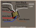
Wires and their position:
Thin Black + thin White wires - most right upper corner
Thick Black + thick White wires - top center of the transformer
Thin Red wire - most top left upper corner
Thick Red wire - most bottom left corner
Thin Blue + thin Brown - most right bottom corner
I measured all the wires, but I include only the pairs that had larger than 0 micro-Henry values :
Thin Black + White wires - most right upper corner = 2.494 uHy
Thick Black + thick White wires - top center of the transformer = 17.66 uHy
Thick White + thin Red wires - center of the transformer + left upper corner = 4.889 uHy
Thick Black + thin Red wires - top center + top left corner = 5.060 uHy
Thick Black + thick Red wires - top center + left bottom corner = 5.062 uHy
Thick White + thick Red wires - top center + most left bottom corner = uHy
Thin Blue + thin Brown wires - right bottom corner = 23.09 uHy
================ Based on the values above, what is the function/reason for it?
When I used my VARIAC Transformer, I applied 120V to the thin Black+White wires (top right upper corner) as input. Here are the outputs I was able to measure (again, if I did not get any volts from other wires, I'm not reporting them here) :
Thick Black + thick White = 15.5 V
Thin Brown + thin Black = 23.5 V
Thick Red + thick Black = 7.7 V
Thick Red + thick White = 7.7 V
Thin Red + thick Black = 7.7 V
Thin Red + thick White = 7.7 V
=============== I'm not sure why the thick Red + thin Red produced NO volts, but last 4 lines, from the voltages I measured above, if I measured them against the other wires, there is this 7.7 V ! ???
============== This transformer is a puzzle that I need help with - I hope one of you might be able to help!
Thank you very much!
Tony
There are several very thick wires and normal wires (I call them thin wires).
The label has this information on it:
430-0195 REV. 1
LS - A8477 - PT
Z150H E154515
CLASS B 130 (degree symbol) C (I assume it is Celsius)
LEI - 4 6A15
The above text/label is exactly as they appear on the transformer. But none is informative, but the 6A (but I don't know what is the number 15 at the end).
Wires and their position:
Thin Black + thin White wires - most right upper corner
Thick Black + thick White wires - top center of the transformer
Thin Red wire - most top left upper corner
Thick Red wire - most bottom left corner
Thin Blue + thin Brown - most right bottom corner
I measured all the wires, but I include only the pairs that had larger than 0 micro-Henry values :
Thin Black + White wires - most right upper corner = 2.494 uHy
Thick Black + thick White wires - top center of the transformer = 17.66 uHy
Thick White + thin Red wires - center of the transformer + left upper corner = 4.889 uHy
Thick Black + thin Red wires - top center + top left corner = 5.060 uHy
Thick Black + thick Red wires - top center + left bottom corner = 5.062 uHy
Thick White + thick Red wires - top center + most left bottom corner = uHy
Thin Blue + thin Brown wires - right bottom corner = 23.09 uHy
================ Based on the values above, what is the function/reason for it?
When I used my VARIAC Transformer, I applied 120V to the thin Black+White wires (top right upper corner) as input. Here are the outputs I was able to measure (again, if I did not get any volts from other wires, I'm not reporting them here) :
Thick Black + thick White = 15.5 V
Thin Brown + thin Black = 23.5 V
Thick Red + thick Black = 7.7 V
Thick Red + thick White = 7.7 V
Thin Red + thick Black = 7.7 V
Thin Red + thick White = 7.7 V
=============== I'm not sure why the thick Red + thin Red produced NO volts, but last 4 lines, from the voltages I measured above, if I measured them against the other wires, there is this 7.7 V ! ???
============== This transformer is a puzzle that I need help with - I hope one of you might be able to help!
Thank you very much!
Tony