Need help with a set of USB pedals for videogames

Thread Starter

Sinkins

Joined Mar 6, 2024
6
Care engineers,

I am not entirely sure if its the right place to ask for help, but i had to start somewhere :)
I have no experience or education related to electronics, so my question might be very odd or/and outright stupid:

I have recently purchased a set of pedals, used for racing simulators on a PC. I have an issue with one of the Axis being inverted in the Windows controllers calibration tool / device manager.
When I am pressing the pedal, it goes down from 100% to 0%, instead of raising from 0% to 100%. I have resolved it by using a software solution, but i wonder if its possible to rewire the axis physically?
Each pedal has 3 wires - ground, 5v and data. Is there any way of inverting the data signal?.. Can I switch ground with 5v? Or add a simple "circuit component combo" of sorts that will invert the data signal?
Most probably it is somehow "hard-coded" in the circuit board, but i thought it is worth asking here.
If it makes any difference - its FREX Sim3Pedal v5.

Any help would be greatly appreciated!
pedals.jpg


I
 

Ya’akov

Joined Jan 27, 2019
10,269
Welcome to AAC.

Inverting the output depends on the nature of the encoder they are using. If it is a potentiometer, you can swap the wires so that the value expected by the program (lowest or highest) when the pedal is ”normal” (that is, not depressed) is appropriate.

If it is a digital encoder of some kind, you might be able to do something similar but it depends on the type and actual part. The one thing I would not do is blindly swap +5V and signal ground.
 

Thread Starter

Sinkins

Joined Mar 6, 2024
6
Thank you for taking time to answer my questions, sir!

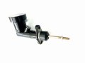
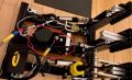
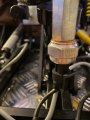
The pedal with inverted axis is using a hydraulic pressure sensor of sorts. Unfortunately, i have no technical information, other than this picture of the cylinder and a picture of the actual pedals.
I would rather not take the risk of "burning" the sensor. Is there a bulletproof way of taking measurements that might help me to determine if its possible to simply switch ground and 5v connection? I have an electrometer at home, although i have very little idea about how to set it up the right way and what to measure.
I am well aware of being illiterate in that regard, and maybe i just need to give up, although if there is some easy way to do it - id like to try :)MasterCylinder0.7.jpgpedals2.png
 
Last edited:

MrChips

Joined Oct 2, 2009
34,982
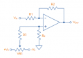
If the output is a varying voltage, you can invert the signal with an inverting amplifier with gain and offset adjustment, something like this circuit:


1709822568763.png

1709822455251.png

A software change is also a simple solution.
 

Ya’akov

Joined Jan 27, 2019
10,269
It is very hard to tell what sort of sensor that is. In fact, I suspect is it not the sensor but an actuator of some sort. Where are the electrical connections made?
 

Thread Starter

Sinkins

Joined Mar 6, 2024
6
If the output is a varying voltage, you can invert the signal with an inverting amplifier with gain and offset adjustment, something like this circuit:

A software change is also a simple solution.


If the helpful folk on this board will help me to figure out if this is indeed an "output with a varying voltage", i would like to try your suggestion! It is exactly what i was hoping to find, in terms of function. Am I right to presume that such a solution is safe, in terms of not sending any current back to the device?

I had no issues fixing it through software, but its one of those gadgets that requires some manual adjustments and tinkering, and it would be very satisfying to fix it "properly".


It is very hard to tell what sort of sensor that is. In fact, I suspect is it not the sensor but an actuator of some sort. Where are the electrical connections made?


It is produced by a smallish Japanese manufacturer. They claim to be developing and manufacturing all their products themselves. Though i doubt they are making their own actuators/sensors etc.

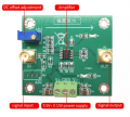
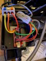
Do these markings make any sense to you, good sir? All three wires ( ground, data, 5v ) are connected to this "module" through the bottom connector.

thumbnail_IMG_6391.jpg
 

Ya’akov

Joined Jan 27, 2019
10,269
It looks like they are using a pressure sensor. The copper washer is one clue. The fact that it looks like a brake master cylinder is another. Maybe it is supposed to be “realistic”? If it is a pressure sensor, I don’t think there is any likelihood a simple wire swap will work.
 

Thread Starter

Sinkins

Joined Mar 6, 2024
6
It looks like they are using a pressure sensor. The copper washer is one clue. The fact that it looks like a brake master cylinder is another. Maybe it is supposed to be “realistic”? If it is a pressure sensor, I don’t think there is any likelihood a simple wire swap will work.
Thank you for clearing this option out of the way! Better safe than sorry.
:)
Put a DMM on the signal wire and measure the voltage as you press the pedal.
Unfortunately, the batteries leaked inside my multimeter - i havent used it for a while...
I will try to clean up the mess or buy a new one tomorrow. Will post results as soon as possible.
Thank you for your time and help!
 

Thread Starter

Sinkins

Joined Mar 6, 2024
6
Put a DMM on the signal wire and measure the voltage as you press the pedal.
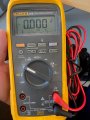
I have borrowed this badboy from one of my coworkers :)
Would you kindly ensure that i have understood the task correctly?

  1. I set the multimeter to DC
  2. I connect the black wire to the ground on the pedals
  3. I connect the red wire to the "data" cable on the pedals
  4. I press the pedal up/down and see if there is any activity on the screen
Do i need to connect the pedals to the PC's USB port while taking the measurements?
multi.jpg
 

Thread Starter

Sinkins

Joined Mar 6, 2024
6
Hey guys!

Here are the results of the measurements:

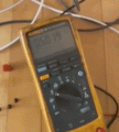
I had black wire on ground and red on "data" wire of the pedal output. PC was turned off. Multimeter was set to auto-DC measurement.

Initially it was showing 0.5. As i was pushing the pedal, it raised to 1.1. ( i was using my hand, so i guess it was about 25% of maximum pressure )

Does it mean I can use "an inverting amplifier" as was previously suggested?


measurements.gif
 
Top