 Facebook
 Google
 GitHub
 Linkedin
I have been scratching my head since couple of days to solve a lcd display issue.
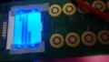
Problem-1: As I read from the datasheet of PCD8544, I can set x, y position to (0, 0) by writing command 0x80 and 0x40. However upon restart when I write these commands and then display any pattern, it seem to be displaying at different location (almost at x=73, y = 0) when I keep on writing then after it continue to write till last pixel (bottom right corner) and then rolls back to top left. If i write exactly 504 data, it covers whole LCD but the start position is not as expected (0,0). Any clue or pointer what could be going wrong? PS: If I don't write (0,0) upon restart and directly start writing data, it starts writing from the first pixel of the lcd as expected
pls see the Scenario1 image
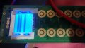
Problem-2: If I want to write some data i.e. write data to first byte of first row, second byte of second row, third byte of third row and so on....
If I dont set the x,y position at start up (first set_xy_pos(0,0)) and only set the Y position within while loop.
I see that it starts to display from first pixel but does not display all the rows.
It just displays 1st, 2nd and 4th rows only rest remains blank
Pls see Scenario2 image
Any clue why it does not display any data on 3rd, 5th and 6th row when I explicitly set the y position?
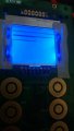
Problem-3: upon restart if I write data 0x01, it makes two pixel ON. MSB and LSB as if I have written 0x81, any clue?
Pls see Scenario3 image
Problem-1: As I read from the datasheet of PCD8544, I can set x, y position to (0, 0) by writing command 0x80 and 0x40. However upon restart when I write these commands and then display any pattern, it seem to be displaying at different location (almost at x=73, y = 0) when I keep on writing then after it continue to write till last pixel (bottom right corner) and then rolls back to top left. If i write exactly 504 data, it covers whole LCD but the start position is not as expected (0,0). Any clue or pointer what could be going wrong? PS: If I don't write (0,0) upon restart and directly start writing data, it starts writing from the first pixel of the lcd as expected
pls see the Scenario1 image
Problem-2: If I want to write some data i.e. write data to first byte of first row, second byte of second row, third byte of third row and so on....
If I dont set the x,y position at start up (first set_xy_pos(0,0)) and only set the Y position within while loop.
I see that it starts to display from first pixel but does not display all the rows.
It just displays 1st, 2nd and 4th rows only rest remains blank
Pls see Scenario2 image
Any clue why it does not display any data on 3rd, 5th and 6th row when I explicitly set the y position?
Problem-3: upon restart if I write data 0x01, it makes two pixel ON. MSB and LSB as if I have written 0x81, any clue?
Pls see Scenario3 image
Attachments
-
3.5 KB Views: 1
-
 40.5 KB Views: 14
 -
 44.9 KB Views: 10
 -
 38.6 KB Views: 12


