 Facebook
 Google
 GitHub
 Linkedin
by development board do you mean the pickit2 module? I am not using the dev board that came with the starter kit, since I had to rewire the socket I just wired the 5 pins from the pickit2 to vcc vss mclr rb7,6 on my breadboard.
I was under the impression that the MCU was a stand alone unit and just needed a Vcc in my final circuit. Can you please explain what you mean by swapping a 4MHz crystal?
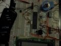
This is how I have it set up, is there some external circuitry on the dev board that I need to wire for this to work?

I managed to read and write to the MCU, but I get no output on RB0,1,2.
I was under the impression that the MCU was a stand alone unit and just needed a Vcc in my final circuit. Can you please explain what you mean by swapping a 4MHz crystal?
This is how I have it set up, is there some external circuitry on the dev board that I need to wire for this to work?
I managed to read and write to the MCU, but I get no output on RB0,1,2.

")


