Facebook
 Google
 GitHub
 Linkedin
Hello everyone!
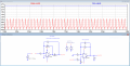
I've been working on a circuit that takes in a 13MHz AC signal and attempts to get a DC voltage out corresponding to it's peak. (or as close to that as possible)
The active half wave rectifier works to perfection, the filter to smooth out the output however, does not work at all.
It's supposed to be an active low pass filter, but even after messing around a bunch with resistor and capacitor values, i never get what i want out.
Here's a pic of the circuit at the moment.

I've also attached the simulation file in case anyone want's to play around with it a bit.
Does anyone spot what I've done wrong here? Am I even in the right path?
Any help is much appreciated")
I've been working on a circuit that takes in a 13MHz AC signal and attempts to get a DC voltage out corresponding to it's peak. (or as close to that as possible)
The active half wave rectifier works to perfection, the filter to smooth out the output however, does not work at all.
It's supposed to be an active low pass filter, but even after messing around a bunch with resistor and capacitor values, i never get what i want out.
Here's a pic of the circuit at the moment.
I've also attached the simulation file in case anyone want's to play around with it a bit.
Does anyone spot what I've done wrong here? Am I even in the right path?
Any help is much appreciated
Attachments
-
3 KB Views: 8