Need help figuring out a 1990 DELCO GM radio Schematic

Thread Starter

stillgrowingup

Joined Jul 15, 2015
219
Good to know as it was hard to tell from the schematic.
Adding R1-R4 will drop the voltage to a safe level with this mod.
Thank you for your input. This seems Feasible now!

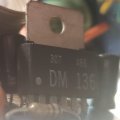
I looked at the actual VR1 Voltage regulator, trying to get a replacement for it. But the Number on the chip pull in NO results from Google. Can anyone here think of replacement for this VR1 part? Actual photo of the part below.20240919_134208.jpg
 

bonked

Joined Feb 12, 2026
1
I was reading your post regarding the delco cassette radio. I have such a radio also. I've got right channel and power switch problems. I was wondering if you could tell me which schematic was shown in your post. Sams? Number? Would it be possible for you to post (or email me ) the complete audio section listing all the capacitors? Thanks in advance.
 
Hi all,

I have this 1990 OEM AM/FM/Cassette Delco radio and have the Radio Repair Schematic for it too. I will be removing the Radio antenna from my car and would like to make AM and FM their own AUX Audio inputs. Meaning, when FM is selected, AUX input 1 is playing. When AM is selected, AUX input 2 is playing. Leaving the Tape deck intact to play my tapes. :)

Its been 10 plus years since I looked and read ANALOG schematics. So I am having difficulties figuring out where I can place the AUDIO inputs to make this happen. There is a clear connection point 'AUD L OUT' & 'AUD R OUT' at plug 'J1' which I have tested and will work, but has only ONE AUX Audio Input. It over-rides ALL Audio ANALOG, AM and FM both which doesn't allow for selectable input. :(

U1 , U2 , and U3 are for the FM section. U4 is for the AM. I do see that pin 19 at the U3 is labeled 'AUDIO INPUT'. I did cut the circuit after 'C50' that leads to U3/pin 19 and soldered a 3.5mm Audio jack at U3/pin 19 to test if it would play through the Radio Amplifier. But I heard nothing. :(

I ask if someone can look at schematic below and guide me to a solution that will allow for (2) external inputs that are selectable when AM and FM.

The following Schematic for the radio section to the ACTUAL Delco radio that I have.

Thank you.

TONY

View attachment 331899View attachment 331900View attachment 331901View attachment 331902
Would this be the schematics/diagram of a Delco Model 16074403? I'm having troubles with mine and want to make sure it's the same before I mess with since I'm not much of a circuit guy or electrician. Thank you if you can help
 

MisterBill2

Joined Jan 23, 2018
27,752
Have you looked at the internal PCB of a recent car stereo receiver?? Even with a correct circuit schematic it will be a serious challenge to locate the connection points.
BUT I have a suggestion for an alternative:A small FM transmitter made for that sort of application, if you want stereo. If you can live with monophonic sound it can be done in a MUCH simpler scheme.JUst a very low powered transmitter, not even one milliwatt, to send the signal into the radio antenna connection. The best part being you do not even need to take the radio out of the car, or open the radio to add the connetion. I have seen such devices for sale, although not recently.
Using that scheme will only need to access the external antenna connection, and not even opening the radio. If you do pen the radio you will find NO ROOM FOR ANYaDD ON CIRCUIT. That has been the case since around 1980. There may even be exactly that type of module/device at automotive Sound Center.
 

MisterBill2

Joined Jan 23, 2018
27,752
Unless the TS is a very skilled radio service tech, I suggest not even opening that radio. They are extremely crowded inside!
An external very low powered FM transmitter connected to the antenna connection will be a much simpler scheme to provide an audio input: Just select FM on the radio and tune it to the frequency of your tiny transmitter. That scheme will be simpler than even just removing the radio from the instrument panel.
 
Top