 Facebook
 Google
 GitHub
 Linkedin
Hi Guys,
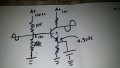
I was hoping you guys can help explain what the attached circuit diagram means to me in a way I can understand. I am new to the world of electronics and plan on taking an electronics program in the Summer for my current employer. I work in the supply chain division right now but hope to jump into the the electronics department.
A friend of mine at work drew this diagram and wanted me to decode what it means. I was hoping you guys can help me out! I would like to know what every symbol means and what this circuit does.
Attachments
-
 2.7 MB Views: 61


