Need an education on mosfet and 555 power needs.

Thread Starter

1Flyer

Joined Mar 5, 2020
5
For a few years I've been tinkering with electronic circuits without much on an understanding, except for resistors capacitors, the basic stuff. Now that the bug has bitten me hard, I decided to take a couple of courses so that I can sound educated, LOL; I am in a course entitled "Introduction to Circuit Analysis", unfortunately mosfet, 555 timers, and others will not be discussed in this class.

I started working on a project that eventually hope it will be a "power off delay". From ACC I found several diagrams on how to make it. My situation is that I plan on using a rechargeable battery (3.7v) but all the circuits I noticed use a mosfet or an 555, and these use 5-15v (per datasheet and designs on ACC).

What I'd like to know is if there is some transistor or timer like 555 that can operate as low as 3v? I looked around with no luck.

Thanks in advance.
 

SamR

Joined Mar 19, 2019
5,526
There are many variants of the tried and true NE555 chip. One variant is the LMC555 CMOS version guaranteed to run at 1.5V. Timers are a bit easier to understand than transistors. Start with reading the Data Sheet for it and building a test circuit.

http://www.ti.com/lit/ds/symlink/lmc555.pdf

Since it can be used as an oscillator to generate sound you may want to combine it with the LM386 amplifier chip and a speaker. However the operating voltage for the LM386 is 4-20V so you may want to use ~5V for it and the timer.

http://www.ti.com/lit/ds/symlink/lm386.pdf

Both are good introductory chips to learn from with a plethora of circuits available for them online.
 

gerty

Joined Aug 30, 2007
1,305
Your load might not be compatible with this, have you thought about using 2 batteries in series..
7.4 v would satisfy the 555 needs, but you haven't mentioned the load yet..
 

Thread Starter

1Flyer

Joined Mar 5, 2020
5
What are you powering that will be turned off, how much current does it draw?
I got the idea from a night light principle; an IR sensor is activated and allows power to pass on and activate a strip of LEDs (~3), keep it on for a short time, then extinguish, even when power is still being supplied from the sensor (plan on using for other projects)

The purpose of this is to notify a hearing impaired person when someone is at the front door. I know there are units commercially available, but how else am I going to learn, have fun, and mostly...keep me out of trouble?

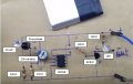
Here's the list of items; go ahead and laugh and joke about my prototype, I don't have breadboards yet, so this is the next best thing. Any other ideas would greatly be appreciated.

Parts:
LED
IR LED
Photodiode
IC LM358
BC547 transistor
10k variable resistor
10k Ω ¼w
3 - 100Ω ¼w
3.7v battery

IR Sensor.jpg
 

Thread Starter

1Flyer

Joined Mar 5, 2020
5
LMC555 needs only 1.5V
http://www.ti.com/lit/gpn/lmc555

Circuit analysis is an important step to understanding the 555. It should give you the tools you need to understand electronics in general... next you will need a solid state electronics course.
Thanks for the advice, I already selected Introduction to Solid State Circuits for the summer semester. Now just need to retain everything, it is confusing at times, but with time and experience it'll work out.
 

wayneh

Joined Sep 9, 2010
18,133
I got the idea from a night light principle; an IR sensor is activated and allows power to pass on and activate a strip of LEDs (~3)
A typical 555 can source and sink up to 200mA and that’s plenty for 3 LEDs if that’s what you’re talking about. The good news of that is that you may not need a transistor to do the power switching because the 555 can do it directly. The low voltage versions of the 555 can’t handle nearly as much current, I believe.

If you can specify the power supply and the load (voltage, current), we can help you with the circuit in between. In general, the lower the voltage below 5V or so, the more challenging the project.
 

Thread Starter

1Flyer

Joined Mar 5, 2020
5
A typical 555 can source and sink up to 200mA and that’s plenty for 3 LEDs if that’s what you’re talking about. The good news of that is that you may not need a transistor to do the power switching because the 555 can do it directly. The low voltage versions of the 555 can’t handle nearly as much current, I believe.

If you can specify the power supply and the load (voltage, current), we can help you with the circuit in between. In general, the lower the voltage below 5V or so, the more challenging the project.
The power supply is a 3.7V Rechargeable 4800mAh LiPO battery. I am using 3 LEDs from the remains of a 15ft strip. I got some
printed circuit boards from Amazon and made the sensor portion, now I need to get the timer and the LED light box built (thanks to 3D printers, save a lot of work)
 

SamR

Joined Mar 19, 2019
5,526
I have a dishpan full of assorted wall warts that have accumulated over the years. They are a varied assortment of voltage and ampacities. Never could bring myself to throw away a perfectly good wall wart after whatever it came with died. They make perfectly good power supplies for breadboarding low voltage DC and some AC circuits.
 

wayneh

Joined Sep 9, 2010
18,133
The power supply is a 3.7V Rechargeable 4800mAh LiPO battery. I am using 3 LEDs from the remains of a 15ft strip. I got some
printed circuit boards from Amazon and made the sensor portion, now I need to get the timer and the LED light box built (thanks to 3D printers, save a lot of work)
Are those generic LEDs, meaning they draw about 20mA each when lit? With a supply at just 3.7V, they’ll need to be in parallel and will draw up to about 60mA. That’s within the capabilities of the low-voltage 555 from TI. No transistor needed.
On the other hand, you could use a BJT instead of a MOSFET to switch the power. Set up the base current to about 5mA (from the 555) and that should be adequate to supply 50mA to the parallel LEDs.
 
Last edited:

Wolframore

Joined Jan 21, 2019
2,619
Couple comments

what keeps that battery from discharging completely in a couple/few days making it unusable?

how much current is going to the base of the transistor and how much do you need?

i would take Sam’s advice and use a wall wart, no battery problem and you can even run that IR led higher current. I believe most of them will run at 40-60 mA.check your datasheet.
 

eetech00

Joined Jun 8, 2013
4,724
Are those generic LEDs, meaning they draw about 20mA each when lit? With a supply at just 3.7V, they’ll need to be in parallel and will draw up to about 60mA. That’s within the capabilities of the low-voltage 555 from TI. No transistor needed.
On the other hand, you could use a BJT instead of a MOSFET to switch the power. Set up the base current to about 5mA (from the 555) and that should be adequate to supply 50mA to the parallel LEDs.
the TS is using a 3v supply so will need a cmos timer and won’t be able to get that much drive current directly from the timer at 3v. But could use a transistor or mosfet to drive the LED(s).

eT
 

wayneh

Joined Sep 9, 2010
18,133
Are those generic LEDs, meaning they draw about 20mA each when lit? With a supply at just 3.7V, they’ll need to be in parallel and will draw up to about 60mA.
the TS is using a 3v supply so will need a cmos timer and won’t be able to get that much drive current directly from the timer at 3v. But could use a transistor or mosfet to drive the LED(s).

eT
If the voltage can drop as low as 3V, the TS may have trouble lightning his LEDs. He said 3.7, which should be ok. I’d still feel better if we understood the load.
That all said, I’d probably choose to use a BJT for this duty, to protect the timer from the load.
 

Wolframore

Joined Jan 21, 2019
2,619
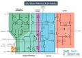
It's true you can get lost in them... but it makes sense once you organize them into blocks... it's two comparators going into a flip flop. The two comparators are connected to a resistive divider which happens to be 5k/5k/5k (not where it got it's name). Then there are two transistor - reset and discharge which controls the RC timer.

1583683034813.png
 

ci139

Joined Jul 11, 2016
2,018
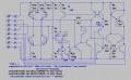
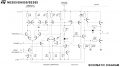
?Q21 ?PNP -- . . . the Puzzle part is to get the Q23 drive all three -- Q21, Q24 and Q14 throughout the specified 4.5 to 16/18 V
(the below requires higher drive and supply currents than the actual thing likely due the speciffics of the 2N2222 2N2907 (and no device scaling (in this v.)))
NE555ic.gifNE555 PHL.pngNE555 ST.png
versus
 
Last edited:

Thread Starter

1Flyer

Joined Mar 5, 2020
5
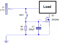
The professor told me to "KISS" the project, I was trying to make it too involved (from lack of experience), so she gave me a list of parts and had me draw it up in Circuit Wizard; I had her evaluate, and after a couple of corrections this is what I got. I found this formula to calculate time time delay: T Sec=1.1*R1*C1.

1584129722248.png

BTW: sw1 will be removed one the actual circuit is built, the IR sensor will act as SW1.

To answer some previous questions:
Yes there are going to be 3 std LEDs for about 18mA each, total of 54mA, and about 100mA for the circuit, to be on the cautious side I am planning on 200mA total.

The battery will be using a re-purposed solar cell that puts out 4.5v 0.5mA
 

ci139

Joined Jul 11, 2016
2,018
they had an item on CarPoint -- years ago . . . a tiny solar-cell that supposedly were able to output 1A ????
. . . . a modern 700mA v. -- the old one was the size of 1 4-th of it or less (i guess they had their specs. incorrect)
 
Top