Need a simple "secure" switched contact circuit

Thread Starter

dts0246

Joined Sep 8, 2010
4
Hi All.
Have tried searching but couldn't find much.
I am looking to use a spare channel of a garage door radio receiver to switch an alarm system on & off.
This is simple enough using just the switched contacts though I would like the circuit and wiring to be a little more secure so as to prevent someone just tapping into it and shorting them.
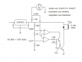
I recall seeing a circuit years ago which was a simple resistor key based switch, where contacts of a relay would open/close based on a specific resistance received from a "key" which was plugged in (using any type of plug you chose).
Any ideas on how to make this wiring more secure would be appreciated.
 

wayneh

Joined Sep 9, 2010
17,496
So you want to combine the functions of a garage door receiver (and presumably a transmitter?) with a key of some sort?
I'm a little confused, since a garage door is already somewhat secured by using a personalized code. It may be easily fooled, but keeps out most folks.

If you're using a "secured" garage door system, what more do you need?
 

#12

Joined Nov 30, 2010
18,224
Here's a crude stab at a lock with a resistor in the key. I'm sure there are ways to polish this, but it's what came off the top of my head. (It might even have a mistake in it, but it illustrates the principle of using a key with a resistance.) If the key is correct, the relay activates.
 

Attachments

Thread Starter

dts0246

Joined Sep 8, 2010
4
Sorry, I worded this poorly.
I am looking to arm / disarm an alarm panel which has simple open / closed contacts.
I have an electric garage door opener which has a spare channel (second button on the transmitter) which I would like to use to control the alarm panel.
Simple enough though as the garage door is on a carport and in the open (can jump the side fence and get to the back of it easily) I do not like the idea of extending the simple contact wires to the outside where they can be easily intercepted/shorted and hence alarm disarmed.
 

#12

Joined Nov 30, 2010
18,224
So...I spent half an hour designing and drawing a resistance key circuit and you didn't even look at it?
 

Thread Starter

dts0246

Joined Sep 8, 2010
4
So...I spent half an hour designing and drawing a resistance key circuit and you didn't even look at it?
#12,
I am out on the road (at work) and posting from my cell (limited service).
I was responding to wayneh’s post earlier and did not even know of your post until just now.
Thank you for taking the time to work on my issue and for putting a circuit together.
From what I can see (on my small phone screen) it looks good.
I assume the round, circled component at the top is the “key” (electrical plug of some sort), which would have a 1K resistor in it?
If the 1K “key” value was to be altered, which components would need to be changed?

Thanks for your time once again.
 

wayneh

Joined Sep 9, 2010
17,496
I'm still confused. If you're arming/disarming the panel with a remote, who cares about wires to the outside?

I was thinking "window comparator" after your first post. #12 had the same idea and did a nice job of drawing it up. I just don't get how a physical key fits into the remote controller plan.
 

Thread Starter

dts0246

Joined Sep 8, 2010
4
With the remote control transmitter I would be switching the auxiliary contacts of the garage door receiver.
The alarm panel arm/disarm contacts (inside house) would be hard wired to the said contacts on the garage door receiver (outside house) and so am worried that anyone could cut the cable and short the wires to disarm the panel.
I am trying to use this method to save having to buy another transmitter/receiver, and also save having to have another remote on my key chain.

With regards to the "key" portion of the circuit I originally mentioned...... in the circuit I was thinking of, it used a plug in "key" (which was any type of audio/electrical plug you wished to use) within which was a specific value of resistors wired between several of the contacts. If a "key" was inserted into the matching socket which had the correct resistance, the relay would open/close.
I was thinking to use a similar circuit with the resistors hard wired at the garage door receiver end and so if anyone was to cut the wiring in between and short it would not operate the relay at the other end (inside).
 

Alec_t

Joined Sep 17, 2013
14,280
I would like the circuit and wiring to be a little more secure so as to prevent someone just tapping into it and shorting them.
I'm not clear how the proposed key use improves security. What prevents someone bypassing the key by 'tapping into' the circuit at the appropriate point? And if you have to use a physical key, doesn't that make the second channel of the remote pointless?
 

wayneh

Joined Sep 9, 2010
17,496
...I was thinking to use a similar circuit with the resistors hard wired at the garage door receiver end and so if anyone was to cut the wiring in between and short it would not operate the relay at the other end (inside).
Got it, thanks. So an open or short of the "exposed" wires would not trigger the arm/disarm toggle. A vandal would need a potentiometer placed in parallel across the severed wires, and could slowly turn the pot until it delivered the right key resistance. But that's far fetched unless they know how the system works.

Is there feedback to show the arm/disarm status?
 
Top