Facebook
 Google
 GitHub
 Linkedin

As I said, it needs tuning.
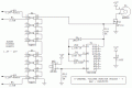
Diodes - The intent of the diodes is to assure that the opto is off when the input is at 1.8 V, but one single Vf drop might not be enough. D1 - D8 should be replaced with 5.1 V zener diodes. This raises the start-of-conduction up to the 6-7 V range. I didn't put them in last night because I don't have a horizontal decal in my library - yet.
Current limiting resistors - I picked 4 mA as an operating current design point as something large enough to guarantee the opto is fully ON, but not drawing unnecessary current from the alarm circuits. In a previous post the TS suggested 15 V as the off state threshold voltage. With 5.1 V zener diodes in series, this makes the current limiting resistors 2.0 K. The opto will start to conduct at a much lower current, and the output will cross the CMOS transition level at a secondary current of approx. 0.6 mA. Depending on the actual opto device used, the input current at 15 V probably can be reduced even more.
ak
Diodes - The intent of the diodes is to assure that the opto is off when the input is at 1.8 V, but one single Vf drop might not be enough. D1 - D8 should be replaced with 5.1 V zener diodes. This raises the start-of-conduction up to the 6-7 V range. I didn't put them in last night because I don't have a horizontal decal in my library - yet.
Current limiting resistors - I picked 4 mA as an operating current design point as something large enough to guarantee the opto is fully ON, but not drawing unnecessary current from the alarm circuits. In a previous post the TS suggested 15 V as the off state threshold voltage. With 5.1 V zener diodes in series, this makes the current limiting resistors 2.0 K. The opto will start to conduct at a much lower current, and the output will cross the CMOS transition level at a secondary current of approx. 0.6 mA. Depending on the actual opto device used, the input current at 15 V probably can be reduced even more.
ak