Need a simple alarm (buzzer) that is triggered when the voltage drops.

AnalogKid

Joined Aug 1, 2013
12,174
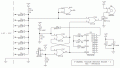
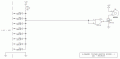
Here is a starting point concept schematic. U1 acts as a simple CMOS inverter with an input transition level of approx. 6 V. IF (yes, this is a big IF) the 12 V power supply is fully isolated and floating, it is safe to connect the monitor circuit ground to the alarm circuit ground.

When any input is pulled down to approx. 5.4 V, the beeper will beep. If this simple approach is OK, then the next step adds the 5 minute silence timer.

ak
Volt-Mon-Buzzer-1-c.gif
 

AnalogKid

Joined Aug 1, 2013
12,174
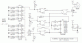
Here is the concept schematic updated with the 5 minute beeper silence timer and decoupling capacitors. U2 Q14 goes high approx. 300 seconds after its Reset input goes low. R5-C2 form a power-on reset input to the control flipflop to allow the beeper to sound whenever U1pin1 goes low. SW1 sets the flipflop, inhibiting the beeper through U1pin2, and starting the timer by releasing the Reset input. After 8192 clock cycles, Q14 goes high, which resets the ff and re-enables the beeper. If U1pin1 still is low, the beeper sounds again.

ak
Volt-Mon-Buzzer-2-c.gif
 
Last edited:
An alternative is to use the LT6700-* version comparitor. Pick the right 1, you can get 2 channels per chip. The inputs are protected to 40 V which is a good thing. There is also built-in hysteresis. below 5 V is what you want. There is a single channel version of the comparitor available as well.

www/proto-advantage.com can mount the devices on a DIP carrier for you.

"Similar" to the micro-power battery monitor. You need two high value resistors to divide 5V (your setpoint) to 400 mV\ and the capacitor.

The open drain outputs can be wire-ored. The next problem is the 5 minute delay. I'd almost consider buying a relay. SSAC being one company. 5 minutes is typically a long time. Timing > about 4 seconds is hard to do analog.

The CD4060B is a decent way of getting long delays.
 

AnalogKid

Joined Aug 1, 2013
12,174
Two LM324's could process 8 channels at 4 channels per chip, with 10 V of hysteresis, but the TS said there is no requirement for a wide detection window.

An SSAC delay relay is expensive. How much does proto-advantage charge for two pieces (one plus a spare)?

ak
 

Thread Starter

Shimra01

Joined Nov 13, 2017
35
Here is the concept schematic updated with the 5 minute beeper silence timer and decoupling capacitors. U2 Q14 goes high approx. 300 seconds after its Reset input goes low. R5-C2 form a power-on reset input to the control flipflop to allow the beeper to sound whenever U1pin1 goes low. SW1 sets the flipflop, inhibiting the beeper through U1pin2, and starting the timer by releasing the Reset input. After 8192 clock cycles, Q14 goes high, which resets the ff and re-enables the beeper. If U1pin1 still is low, the beeper sounds again.

ak
View attachment 152342
Awesome. This is great stuff. I am still not sure that I can tie the 2 grounds together as I have no clue how the other networks power supply is build up.
 

AnalogKid

Joined Aug 1, 2013
12,174
I am still not sure that I can tie the 2 grounds together as I have no clue how the other networks power supply is build up.
IF your own power supply is fully floating
AND IF no part of your circuit contacts any other circuits with their own ground systems, or earth ground
THEN you should be ok.

ak
 
@AnalogKid

FYI

Assuming this is the correct adapter:

TSOT-6 (1.65 x 2.97 mm body, 0.95 mm pin pitch) to DIP-6 (300 mil body, 0.1" pin pitch) adapter. body is way too small.

http://www.proto-advantage.com/store/product_info.php?products_id=2200230

$3.19 for the kit of parts
$6.00 for assembly
$1.00 extra for machined pins
$6.25 approx for the IC which they will procure from Digi-key

AK you avoid the typical max input problem. You don't want the system to fail if power is off and an input is applied.

For reference:
Don't forget stuff like bypass capacitors, reverse polarity detection, terminal blocks, etc.

Some "systems" may have an alarm that's loud and a "local alarm". "Alarm silence" may stop the loud alarm, but a local buzzer continues to operate. I think in some cases the alarm goes into trouble.

Any opto-isolated design would add expense. Typically, you would connect an optoisolator and resistor across each lamp. You may need from 2-20 mA from the original system per lamp to make it work. There are LED lamp replacements for many standard lamps. Some 24 V lamp replacements will operate on 24 VAC and 24 VDC.

As a stupid aside, one company (Alcoswitch) decided to change the design of their button/switch so an O-ring trapped the heat of the incandescent lamp so that the plastic deteriorated. I had over 150 of these in systems I designed. I had to start moving the replacements to iDEC with LED lamps for better reliability.

When I designed a shutdown system in the 1980's, I really didn't know any better. I used a bunch of 3PDT relays. The contacts used functioned as latch, alarm loop and indication. A momentary contact closure turned on an alarm point. I had about 8-10 points.

The "other guys" built a system that did not latch the alarm condition and that was really annoying. They used a Normally Closed loop designed as a "sequential interlock". They also decided that the air velocity alarm (which gets dirty) would not have a display. So, you had shutdowns due to dirty sensors and you would not know what did it. A power glitch would also shut the system down as would my system.

On two inputs, one from a toxic gas monitor and one from the fire alarm panel, I did indicate the current state with a LED. OFF was tripped.
It really helped because we could not reset my system until the fire alarm was reset and occasionally we kept my alarm/shutdown system running during fire alarm testing. During those times, the system was inactive, but we wanted to keep the chamber under vacuum.

In some respects having a module that would have done a monitored contact and trouble indication would have been nice. The system worked twice and that's what really mattered.


$6.00 Adder for assembly
 
You did. Assuming the 12 V supply is zero and the alarm supply is 24 V. D1-D8 won't let the input to U1A or U1B exceed 0.62-0.72 V or the diode drop of the IN914. http://www.onsemi.com/pub/Collateral/1N914-D.PDF

The input voltage range of all inputs https://www.ti.com/lit/ds/schs015c/schs015c.pdf are -0.5 V, to Vdd +0.5 V. When Vdd is zero, bad things can happen.

You don't have that as a problem, because a positive voltage can't get to the inputs U1A or U1B with Vdd =0; i.e. The 12 V supply off.
 

AnalogKid

Joined Aug 1, 2013
12,174
Your explanation is not clear. The pull up resistor for the diode inputs and U1 share the same power supply. When that supply is 0 V, the input to U1 pulled down to 0 V by R3. The minimum input voltage is stated to be +1.8 V, so all input diodes are reverse biased.

The 1N914 / 1N4148 is rated for 100 V repetitive reverse voltage, so it easily can withstand 24 V with exceptionally low leakage current. The datasheet says the typical leakage current at 20 V is 20 nA. This is close enough to a 24 V rating for this discussion. This works out to 2.5 mV across the 100K resistor, or 20 mV if all 8 inputs are high and the 8 diodes are exactly perfectly matched in their reverse conduction characteristics. That is only 4% of the Vdd+0.5V rating for the input.

D1 - D8 have no effect on U1B.

ak
 

Thread Starter

Shimra01

Joined Nov 13, 2017
35
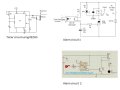
Sorry guys I was not online for a day plus. Back now. Interesting discussions and some good designs considerations. However I am now getting to a point that I need to start prototyping as I have very limited time to install (unless I can get the customer to give me another extension...but not sure as they really pressing for this to be installed). What design do you think would be the best for me to prototype and test in next 24hrs? Here are some designs I found searching on the internet, thinking I can bring this all (including the designs here) together into a single design? I am still struggling with 1. the grounding issues and 2. how to have the hi - lo trigger my alarm. Maybe I am just to stressed now about this as I have been on this project for days and my deadline is nearing.... sorry guys I know you all doing your best to help and I appreciate it all.
 

Attachments

AnalogKid

Joined Aug 1, 2013
12,174
Optical isolation increases greatly the current being drawn out of the alarm circuits by the buzzer circuit. I mentioned this before - can each alarm circuit supply 4 mA to drive the LED in an optocoupler? If so, that changes the input part of my circuit, but not the output. 300 seconds is a loooooong time for an R-C timer circuit, no matter what the timer chip is.

Optocouplers - yes / no ?

ak
 

AnalogKid

Joined Aug 1, 2013
12,174
Quickie update to use optocouplers on the inputs. Might need a tune-up.

AND, BTW - If this circuit looks complicated because of the discrete flipflop, there is a way around that. One quirk of using the CD4060 in this type of circuit is that it would power up in the inhibit state. That is, when first powered up, the beeper will be silenced for 5 minutes. After that, the beeper will be enabled and everything will perform as requested. If you don't mind a power-on inhibit cycle, all four sections of the CD4001 go away.

ak
Volt-Mon-Buzzer-3-c.gif
 

Thread Starter

Shimra01

Joined Nov 13, 2017
35
Optical isolation increases greatly the current being drawn out of the alarm circuits by the buzzer circuit. I mentioned this before - can each alarm circuit supply 4 mA to drive the LED in an optocoupler? If so, that changes the input part of my circuit, but not the output. 300 seconds is a loooooong time for an R-C timer circuit, no matter what the timer chip is.

Optocouplers - yes / no ?

ak
I want to try the opto route. If test show it doesnt work due to much power requirement from the existing circuit then we change.
 

Thread Starter

Shimra01

Joined Nov 13, 2017
35
I will buy the parts needed as per latest design and put it all together for testing tomorrow. Will update you on the outcome.
Any last minute changes and or updates let me know.
I will replace D1-D8 and D9 by 1N4148 types as I have these plenty in stock and the opto I will replace by EL817 types again as I have plenty in stock. If better I can also use 1N4007 for the diodes. Do let me know if this will be ok. Thanks for your help guys and I will be back with an update soon.
 

bertus

Joined Apr 5, 2008
22,953
Hello,

@AnalogKid , I do not see the current limiting resistors for the optocouplers in your schematic in post #33.
The datasheet shows an absolute maximum led current of 60 mA.

@Shimra01 , Also the EL817 has a maximum allowed current of 60 mA.

Bertus
 

Thread Starter

Shimra01

Joined Nov 13, 2017
35
Hello,

@AnalogKid , I do not see the current limiting resistors for the optocouplers in your schematic in post #33.
The datasheet shows an absolute maximum led current of 60 mA.

@Shimra01 , Also the EL817 has a maximum allowed current of 60 mA.

Bertus
ok so based on 21V input and a 5mA Vf current for the opto I should calculate a resistor and add in the opt circuit? So if correct R should be 4.2K. correct
 
Top