 Facebook
 Google
 GitHub
 Linkedin
I am trying to create a 1 Hertz oscillator using NAND gates.
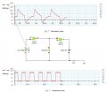
I have created the following (image attached) NAND gate oscillator using 2 gates. Looking at the chart in the image we can notice that the input to the first NAND gate IC1a peaks at around 17v. The circuit supply voltage is 12v. When I run this simulation in Yenka the first NAND gate IC1a blows up as the input is 17-12 = 5v above the supply voltage. As the per the IC ratings in the data sheet the input pin voltage cannot be more than +/-0.5V of supply voltage.
What is wrong in this circuit?
Attachments
-
 71.1 KB Views: 272


