Facebook
 Google
 GitHub
 Linkedin

Hi All!
Currently experimenting with high voltage mosfets in AC circuitry.
The problem: my first mosfet blew up. WHY?
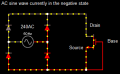
Attached in this post is the schematic that I had setup.
I understand that during full wave rectification, when the AC wave is in its negative state, produces a negative charge on the netrual side of the circuit and the positive side of the ciruit remains neutral, giving the illusion on the oscilloscope that the positive side of the fully rectified circuit always has a positive potential difference on both negative and positive state of the sine wave.
Because of this, if the base is not connected to anything and is discharged, when the sine wave is in its positive state, no current flows through the mosfet because both the source and the gate remain neutral. But when the neutral side of the circuit develops a negative potential difference, then all of a sudden the voltage difference between source and gate is now +240V, which turns on the mosfet and blows it up.
BUT... if the base was negatively charged along with the source, then the potential difference would be 0v.
Is my theory sound? Am I missing something? Why did the mosfet blow up?
The mosfet used is STP9NK50Z.
Looking at the datesheet, under Vdgr in the Absolute Max Rating, I don’t fully understand what Rgs is. It says 20k ohms. Does that mean 125ma of current will flow through the gate to drain if the voltage of drain is 240v? Thats about 3w of heat! so i dont think this is true. what does it mean? or does it mean i need a 20k ohm resistor on the gate (which doesnt make sense to me either)?
Currently experimenting with high voltage mosfets in AC circuitry.
The problem: my first mosfet blew up. WHY?
Attached in this post is the schematic that I had setup.
I understand that during full wave rectification, when the AC wave is in its negative state, produces a negative charge on the netrual side of the circuit and the positive side of the ciruit remains neutral, giving the illusion on the oscilloscope that the positive side of the fully rectified circuit always has a positive potential difference on both negative and positive state of the sine wave.
Because of this, if the base is not connected to anything and is discharged, when the sine wave is in its positive state, no current flows through the mosfet because both the source and the gate remain neutral. But when the neutral side of the circuit develops a negative potential difference, then all of a sudden the voltage difference between source and gate is now +240V, which turns on the mosfet and blows it up.
BUT... if the base was negatively charged along with the source, then the potential difference would be 0v.
Is my theory sound? Am I missing something? Why did the mosfet blow up?
The mosfet used is STP9NK50Z.
Looking at the datesheet, under Vdgr in the Absolute Max Rating, I don’t fully understand what Rgs is. It says 20k ohms. Does that mean 125ma of current will flow through the gate to drain if the voltage of drain is 240v? Thats about 3w of heat! so i dont think this is true. what does it mean? or does it mean i need a 20k ohm resistor on the gate (which doesnt make sense to me either)?
Attachments
-
 5.3 KB Views: 41
Last edited: