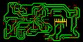
My Soldering station

milanca

Joined Jun 18, 2011
7
Thanks R!f@@ for your help. Of course, when you get a chance, no rush. I am a developer/coder by trade and i also work biggest part of the day (and night). I will measure some references. Hope if will help trace down whats wrong with my circuit. Transistors are good (i checked them), also lm358. I will see if tl431 or lm393 are not faulty maybe.
 

milanca

Joined Jun 18, 2011
7
Hi,

There is no need R!f@@ to go through the pcb and look for the errors buddy. PCB is fine. I grabbed a little time today to check it between the work and while baby was sleeping :) It was damn lm358. I swapped it with another one thinking it was okay but found out that it was faulty, it was not switching off. When i increase the temp. on the pot it starts heating but doesn't turn off. When i decrease it then it does turn off, so lm393 was working but not lm358. Lucky me i found another one in my components box.

Temperature regulation is working beautifully now. Can't find the temperature probe i got along with the multimeter but i trimmed it just to barely start to melt the solder on the very minimum of the pot. I believe its somewhere around 190C. Increasing the temperature goes beautifully linear and its pretty steady. I am very much satisfied with the result. So the PCB file (sprint layout) i posted earlier is absolutely okay (and tested) if someone wants to use it. Board size is 10x5 cm.
Thank you r!f@@ again for this beautiful project.
 

Thread Starter

R!f@@

Joined Apr 2, 2009
9,918
Hey
I did checked ur board. I found two errors, but since you said it is working I am confused.
Still I will point them out to clear ur or my mistake :D

In Milanca's PCB the heater is connected between 12V. It should be between 0VAC and 24VAC or MT1 (of Triac) not MT2.

The Triac should get 24VAC not 12VAC with reference to 0V. This 24VAC should be connected to center pin or MT2 not to MT1. I double checked per data sheet.

This is how the triac is driven but in ur case I wonder why it is working.
Can u take measurements on the heater AC voltage when heater is on Milanca.

Since I have finished my proto PCB I am attaching them.
I do not have the luxury of doing PCB as I wish.
I would be grateful if any one did this if he/she wishes to make the circuit only of my proto.

It is only 1cm bigger than Milanca's I believe. But it has the benefit of Triac heat sink, more IC decoupling caps. Ground plane which I think is cooler to look :D and Fuses on board.

Nicer layout too :p

{ed}
Will add files after testing the prototype. Clad is on the way
 
Last edited:

milanca

Joined Jun 18, 2011
7
Hi R!f@@,

Please take a closer look at my design. Transformer is 2x12 with single center tap(0) , so 3 leads from the secondary. I am using one AC12v lead and 0 for the bridge, but using two AC 12V leads for the heater, which give 24V.
 

Thread Starter

R!f@@

Joined Apr 2, 2009
9,918
Hi R!f@@,

Please take a closer look at my design. Transformer is 2x12 with single center tap(0) , so 3 leads from the secondary. I am using one AC12v lead and 0 for the bridge, but using two AC 12V leads for the heater, which give 24V.
Now I am wondering if the triac is firing properly ?

Do you need a PCB?
Thanks Jen. Not for this cause my original one is much bigger with two iron controllers plus hot gun controller with temp displays. I would want to make a PCB when all the schema's are ready.

I said if any one would do is tht he/she wishes to make it if interested in my design as Milanca. It would save me some money atleast u know to test the design. Cuase u guys can make it with around a few bucks which for me would be around 100 USD

I am trying to make PCB's cause I ordered a few clads to fool around to see whether I can make them.

You know it is a bit too much to get a post from Norway. It's not that I do not appreciate what you do for me. I really do. You are one of my best buds u know...:).

Money making is not easy these days here. :( It was couple of years ago though. Politics is killing the less rich people.
 

Thread Starter

R!f@@

Joined Apr 2, 2009
9,918
Hi R!f@@,

Please take a closer look at my design. Transformer is 2x12 with single center tap(0) , so 3 leads from the secondary. I am using one AC12v lead and 0 for the bridge, but using two AC 12V leads for the heater, which give 24V.

Did you take any measurements on the reference voltage changes & heater voltage?
 

milanca

Joined Jun 18, 2011
7
Hi R!f@@,

Yes buddy, you were right. I did a mistake on my pcb, only in the file. Triac part with resistors and a block cond. i assembled on a small piece of proto board and connected it with the main board. It was properly assembled but i did a mistake later drawing the pcb. Anyways here is the revision.

Controller is working beautifully. Reference is rock solid, 4.9V. On the heater there is 26V AC.
 

Attachments

Thread Starter

R!f@@

Joined Apr 2, 2009
9,918
One more error or may be not.

The heater should be at zero not 12V....!

I am wondering why you are getting 26VAC between 12VAC & 12VAC ? :confused:

With 12-0-12 VAC Tx it should be 0VAC - 12VAC - 24VAC...!
Still the heater should be connected to 0VAC. Ur drawing have a mistake I presume.
 

milanca

Joined Jun 18, 2011
7
No, my transformer is 12-12-0, i connect it between 12 and 12 (24AC) .
It is rated 12V on each lead but it actually gives 13VAC on each of two leads, that's why there is 26 on the heater.
 
Top