my little lab

Thread Starter

Eric007

Joined Aug 5, 2011
1,158
@john P: thanx for the above!

Sorry 4 da stupid question I'm about to ask:
- so you mean I can write the chip with your Hex file the way it is and it will run? I'm asking this coz they don't have da same pins configuration...

- another thing is I've never program the chip straight from the hex file...would you mind showing me the steps to do so? Coz what I usually do is: I have my asm file, build it then pug errthang and selecting pickit3 programmer then click the program button...and that's it!

- regarding your code, you have configure port c as output 'set_tris_c(ob00000000)' and I can see somewhere u initialise portc with zero 'portc = 0'
And I'm wondering what's 'portc_shadow = 0xF8' for??
And what's the 'set_tris_a(0b00111111) and set_tris_b(0b00010000)' for?

Sorry for being a pain...what I want is trying your hex file and see ie run...also make my assembly version work...then tomorrow I can talk about another story!

I'll post my version right after your comment!

Regards,
 

Thread Starter

Eric007

Joined Aug 5, 2011
1,158
How does one test a stepper? I mean without a microcontroller...just on its own with power supply?? I want to try it if possible...I am really tired of this thread...too close to g*#e *p...
 

Thread Starter

Eric007

Joined Aug 5, 2011
1,158
I would be done if the provided code was in assembly...would be easier for me to track it...

Anyone to provIde the assembly version of John for the Pic16f690??

Regards,
 

John P

Joined Oct 14, 2008
2,068
I've already sent you the assembly language listing--it's in the file S_HAND.LST. But it's a file that contains the C source interspersed with the assembly language and the hex codes. That's so you can see which lines of the program will make the processor work hardest, and also how fast the memory space is filling. These things aren't right in front of you if you program via a compiler.

I can't help you with how to get the hex code into your processor. I have a variant of the "Kit 149" product and it takes the hex file; maybe your Pickit3 is different.

Regarding 'portc_shadow = 0xF8' and set_tris_a(0b00111111) and set_tris_b(0b00010000), those are all leftovers from another program which I copied the initial code for S_HAND from. They don't do any harm, so just ignore them.

Sample from LST file:

0000 00552 .................... if (++ct < 125)
007B 0AAC 00553 INCF 2C,F
007C 307D 00554 MOVLW 7D
007D 022C 00555 SUBWF 2C,W
007E 1C03 00556 BTFSS 03,0
0000 00557 .................... continue;
007F 2877 00558 GOTO 077

The quickest and easiest way to test a stepper is to connect the common lead to the power supply, then touch the other leads to ground, one at a time in turn. If you get the sequence right, the motor should move in a series of steps.
 

Thread Starter

Eric007

Joined Aug 5, 2011
1,158
I just tested my motor manually just as you explained and I noticed the following:

- when I ground the yellow and the orange one at the time, the motor steps clockwise.
- when I ground the black and the brown one at the time, the motore steps couterclockwise.

BUT the biggest observation is that there is a complete revolution after 24 steps!!!
Does that mean that my motor is rated 15 degree/step???

Regards,
 

MMcLaren

Joined Feb 14, 2010
861
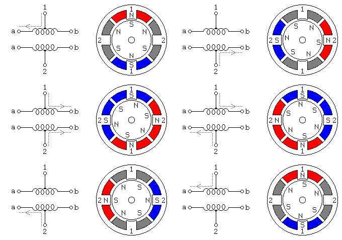
You may not have found the correct sequence yet. Did you spend any time at the "Jones on Stepping Motors" site? Did you see the animated gif for the unipolar stepper motor and did you look at the stepping sequences in the text?

 
Last edited:

John P

Joined Oct 14, 2008
2,068
In MMcLaren's diagram, the "common lead" is actually two wires, 1 and 2. Send them both to the power supply. It's confusing that there are two a's and two b's, but call them a1 and b1, and a2 and b2. Then the energizing sequence would be a1, a2, b1, b2.

If you're in any doubt about which wire is which, use an ohmeter. From input to one coil's connection would be 70 ohms or whatever you have (my motor is about 90 ohms): a measurement across two coils would be twice that.
 

SgtWookie

Joined Jul 17, 2007
22,230
All right Eric, I'll put the files in the Public folder on my Dropbox account, rather than sending you a PM about PWM. Anyone who wants this can have it, but if you make lots of money off it, I expect a share.
Cool. :)

Edited to say that the numbers listed in that article for microstepping duty cycles do agree with my spreadsheet.
It's always nice when you find someone else has arrived at similar conclusions. ;)
But if you use the technique Sgtwookie suggested where adjacent phases are complementary (i.e. the two duty cycles always add up to 100%) you won't get constant torque. That's only possible if you can give two phases independent duty cycles, which would mean more complex programming.
The suggestion I presented certainly has weaknesses; but it was the easiest way I could think of to use just one hardware PWM to drive two phases, and not have to get into real-time programming of a PWM loop, without the complexity of manipulating a 3rd I/O pin on top of that.

It's more or less the equivalent of stepping just one phase at a time; not even a normal full step (where two phases at a time are changed.)

One could get significantly more torque from the motor if one phase were turned on, and the phases on opposite sides of the phase that's on were PWM'ed. The torque will still vary, but it's a way that one can get finer control of the step angle without losing a lot of torque.
 

MMcLaren

Joined Feb 14, 2010
861
In MMcLaren's diagram, the "common lead" is actually two wires, 1 and 2.
That's not my diagram. It's from the Jone's site. And he references the windings as 1a, 1b, 2a, and 2b. He also shows a single step sequence and single step "torque" step sequence (two coils on during each step).

I used the information on that site several years ago to correctly identify the windings on some 200 step/revolution (1.8°) steppers.
 

Thread Starter

Eric007

Joined Aug 5, 2011
1,158
Thanks guyz for all your comments...

John P, maybe you are right...I think I shouldn't play with stepper motors yet...ain't my level yet... I GIVE UP on this thread!!!

Will nomore talk about this!

Regards, Eric
 

MMcLaren

Joined Feb 14, 2010
861
Eric, I'm curious. You seem to have an agenda. That is, you say you have two more projects you'd like to do and, so far, as soon as you get working code for one project, you're off on the next project. I would have expected you to add features and experiment with each project a bit more and so I wonder now if you're working on a list of projects which are a school assignment or something like that?
 

Thread Starter

Eric007

Joined Aug 5, 2011
1,158
@MMclaren:
First of all, I will be in this forum until I die and discussing about complexed problems!
Also I will revisit each single project I previously discussed on this forum adding more complex features to implement...for instance for this stepper motor I was thinking of adding 2 pushbuttons for direction (clockwise and counterclockwise), potentionmeter,...but fact is I can't make the simple one without feature work...,so how can I add those feature Mike?

Tomorrow or after tomorrow I'll be talking about something else even if this one doesn't work... And so on...

If I stop discussing about PIC microcontrollers and embedded system, that means I'm dead and I don't think I'll die anytime soon...

Maybe I wana know too much too early...
Soon I'll be discussing about remote controled cars with cameras and controlled choppers like the ones our parents used to buy us when we were kids...

Anyway I like this forum and its people!

Regards, Eric
 

Thread Starter

Eric007

Joined Aug 5, 2011
1,158
Oh! I forgot something, when I said 2 more projects to discuss I meant after the next 2, I will come back to the first one adding more complex features till the last has been revisited...and talk about big boys projects! Das what I meant...anyways...

Regards,
 

Thread Starter

Eric007

Joined Aug 5, 2011
1,158
Eric, I'm curious. You seem to have an agenda. That is, you say you have two more projects you'd like to do and, so far, as soon as you get working code for one project, you're off on the next project. I would have expected you to add features and experiment with each project a bit more and so I wonder now if you're working on a list of projects which are a school assignment or something like that?

:D lolol...I think you'll have a headache if you start wondering 'who's asking what for what'...lots of people ask for help in this forum for different reasons...

Some are stuck with a task assigned to them at work...
Some are stuck with their school assignment...
Some are stuck with a design they doing for fun...
Some want to know how things are made/done...
Some some some...

The point is: it doesn't really matter why why...if one can/is willing to help...it ok and if one can't/ isn't willing to help...its still ok...life goes on...

Some people helping today on the very same thang they were stuck with 5/10/30 years ago...coz now it a piece of cake to them now...so that's wassup!!

Anyways...

Y'all take care...

Regards,
 

MMcLaren

Joined Feb 14, 2010
861
Hi Eric,

I apologize if I've put you on the defensive. It just seemed strange to me that as soon as you got working code for project #1 and project #2 you pretty much abandoned those projects and started a new one. Now after only a few days on project #3 you're going to abandon it and move on to another project. You seem unable or unwilling to spend more time on project #3. Since you also mentioned you have another two projects waiting, it seems (to me) you have a list of projects and a time table and that's the reason why I asked if these were school projects. Knowing whether or not a request concerns a school project affects how forum members respond to the request. Most members will want to provide advice, direction, and guidance to a student rather than provide him/her with a finished program...
 
Last edited:

Thread Starter

Eric007

Joined Aug 5, 2011
1,158
Back to this thred with a running code!!! Hahahah....

Check code attached...

But I suspect my motor to be a 15 degree/step as there's a complete revolution only after 24 steps!!

Also, the motor is not self starting sometimes and sometimes it stops and I have to move it so it can carry on...

Also wheter I use 100, 20, 60, 60, 20 or 100, 25, 58, 58, 25...as duty cycle there's no change!!

Can somebody tell me which duty cycles should I use to get 6 degree/secon?
Also, why does it stop running some time??
Notice that the code is not really commented but...
And I can't forget that this code is a pure conversion of John P code!!!
But I consider this thread to be close...so if u wana comment it cool if not it cool too...
 

Attachments

John P

Joined Oct 14, 2008
2,068
That's nicely formatted code. If you must use assembler, that's the way to do it. Though I hate to say it, one major advantage of the AVR processors over the PICs is that there's a pretty decent free compiler available for the AVR.

With your motor wiring there, I believe that you've wired it wrong. In the diagram MMcLaren posted, if you operated phase 1a followed by 1b, you'd see exactly what you describe--a step twice the size it should be, that may need a nudge before it occurs and could go in either direction. Another way this could happen, if you're running the motor off a processor, is that some of the phases may simply not be powered.
 

Thread Starter

Eric007

Joined Aug 5, 2011
1,158
That's nicely formatted code. If you must use assembler, that's the way to do it.
Thanks!

Though I hate to say it, one major advantage of the AVR processors over the PICs is that there's a pretty decent free compiler available for the AVR.
The pickit3 comes with a C compiler...

With your motor wiring there, I believe that you've wired it wrong. In the diagram MMcLaren posted, if you operated phase 1a followed by 1b, you'd see exactly what you describe--a step twice the size it should be, that may need a nudge before it occurs and could go in either direction. Another way this could happen, if you're running the motor off a processor, is that some of the phases may simply not be powered.
i doubt it coz there's only 4 wires (the 2 center taps are connected to power) and it is easy to try all different possible combinations of wires...and i did...its only 24 steps for one revolution (wheter clockwise or anti-clockwise)...

but it good enough for now...

i still have to read all the links you provided for better understanding of how it works for future BUT next time i come with a discussion of stepper motor i'll make sure that im ready for that...and the specs will be as complex as possible....

Kindly regards,
 
Top