My breadboard broke....

Thread Starter

Oxbo Rene

Joined Feb 20, 2009
201
Guess I have to admit my ignorance here.
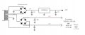
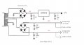
My little breadboard /w/ power supply (+5v@1A), adj(+15v@.5A), adj(-15v@.5A), is broke !
http://www.mpja.com/prodinfo.asp?number=17710+TE
Used it yesterday, been working fine, etc. Got up this morning, had (0v) on the adj (+15v) meter.
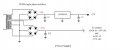
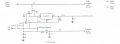
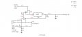
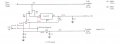
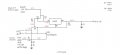
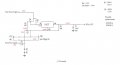
Oh boy ! I get to fix it !.Is really a simple looking board. Has LM317T voltage regulator for the +15v, LM337 for -15v (-15v is still working fine), the LM 317T had input voltage (approx 20v) but no output, no adj, not a problem, run down to radio shack, purchase a new one, replace= zilch.
Long story short, messing around, I happened notice I had the hot wire run to the breadboard, pulled it off, voltage shot up to +18v on the meter. I must've had it shorted , but how? worked fine last night, hadn't done anything since, anyway, now I got 18v instead of 15v,
"AND" the adj pot doesn't do anything to adjust it.
OK, I had originally thought about taking the pot out of the circuit and replacing it with a fixed resistor, that way I'll have a fancy pot to use on the breadboard (install terminals), now I'll just go ahead and put a resistor in that cuts voltage down to 12v.
Problem, during my figuring to find proper value of resistor (came to 14.4M). I had it sitting there running at 12v, put my little peizo buzzer on it to try it, and the voltage dropped to 8.5v, buzzer doesn't work.
So, I have no constant voltage.
I have looked and prodded around everything, looked high and low on the net for knowledge, schematics, am finally "lost".
I'm thinking about buying a similar power supply ($6.00) and just replacing it (is a little bit better),
http://www.mpja.com/prodinfo.asp?number=17721+PS
but, this one is just too simple a circuit to give up on.
So, am appealing to you guys for some knowledge, etc.....
The LM317T has voltage on all the pins, similar to the LM337, both circuits are right there together looking like twins, and yet, I can't find the cause.
And, there are a couple of small transistors (STS9014) that play a roll, connected to the "in" and "Adj" pins.
If I have to I'll have to go out there and get really into drawing the circuit out.
Hoping that someone can give me a quick fix instead of getting bogged down, etc, etc.
Thanks guys..
Oxbo
 

SgtWookie

Joined Jul 17, 2007
22,230
Make a schematic of the complete power supply, if only to document "what is", before you progress to something different.

If you change things willy-nilly, how can you hope to fix something? :confused:

LM317's aren't that complicated.
 

Thread Starter

Oxbo Rene

Joined Feb 20, 2009
201
Tx's Sarge;
Will get on that first thing in the morning.
I was thinking, when I changed the LM317, the breadboard might've been shorted, then I found the short, perhaps the new one got fried too.
I figure it is the source for the constant voltage, and I don't have constant voltage now. I wonder it I put another in if I might luck up and get it fixed?
I sent MPJA an e-mail as to possibly obtaining a schematic, but, no reply, I really doubt they'd have access to one, etc.
I appreciate your input, will be awhile till I get this thing drawn out.
Oh yea ! There is a 1 watt resistor in the circuit with the color code of Green/Black/Silver, I read where the third band being silver means "Divide by 100" if I interpret it right, that would be a .5 ohm, 1 watt resistor, seems odd.
OK, I'm on it ..........
Oxbo
 

HarveyH42

Joined Jul 22, 2007
426
Might pick up the data sheet for the LM317, examples of many different ways to use it. Haven't looked at it in a while, but probably has the configuration you are looking for, and the math to get what you want out of it.
 

thatoneguy

Joined Feb 19, 2009
6,359
From reading the procedure, is it possible that the shorted breadboard is what destroyed the first LM317, which you replaced and tested, which led you to the short.

Did the new LM317 get damaged from the same short? Might want to use a meter on the breadboard to make sure the rails aren't still shorted.

15M is a huge resistor. In general, resistors are for current limiting, or a voltage reference, not for a power supply. A 1M resistor would drop 1V per microamp of current through it.

<grumpyoldman>
Finally, prototype equipment should be turned off when not in use. Fire dangers are real. If the regulator didn't fail open as it did, the transformer could have smoked, or worse.</grumpyoldman>
 

Thread Starter

Oxbo Rene

Joined Feb 20, 2009
201
OK,
Here's the circuits as I (hopefully) traced them out.
Remember, +15V circuit is stuck on 18.5V and pot doesn't work.
-15V circuit is perfectly good
Both pots turned to max voltage output.
Not sure if I have the Xformer/rectifier ckts drawn correctly.
Observation ->
#1- R5 has 10.4V on one side and -27V on the other = ?????
#2- Q5 emitter has 10.4V, whereas Q3 has 1.3V = ?????????
I suspect Q5 as being faulty......
MISTAKE = Q3 & Q6 (S9015) are PNP transistors, pinouts are the same.......
Couldn't find datasheet for S901x, so looked at STS901x.....
2W08 instead of W208.....
 

Attachments

Last edited:

SgtWookie

Joined Jul 17, 2007
22,230
OK.
In your leftmost drawing, both bridge rectifiers need to be rotated 90° to the left; otherwise there is a conduction path through both bridges that would short the transformer's secondary windings.

Where is the -15 supply coming from? Or did you mis-draw the +27v supply?

In the middle drawing, Q6 is depicted as an NPN transistor. It should be depicted as a PNP transistor.

In the rightmost drawing, Q3 is depicted as an NPN transistor. It should be depicted as a PNP transistor.

Are both R3 and R7 actually 200k Ohms? :eek: That's a lot! They SHOULD be somewhere between 120 Ohms and 240 Ohms.

Check to make certain that R7 is not burned open. The voltage between the LM317's ADJ and OUT pins should be nominally 1.25v, with a range of 1.2 to 1.3v. Right now, you're measuring 8.2v (18.5-10.3), which is not good. If R7 is OK, then replace the LM317.

[eta]
I re-drew what I think that your leftmost diagram should look like. Look at it and see if you agree.
 

Attachments

Last edited:

Thread Starter

Oxbo Rene

Joined Feb 20, 2009
201
Looking closely,
R2 & R6 = Brn,Blk,Blk,Brn,Brn = 1K
Reversing the order = Brn,Brn,Blk,Blk,Brn = 110 ohms
http://samengstrom.com/nxl/10116/5_band_resistor_color_code_page.en.html
R3 & R7 = Brn,Blk,Blk,Orange,Orange = The 5-band color code calculator won't let me use the last Orange color, so, went with->
Orange,Orange,Blk,Blk,Brn = 330 ohms.
Trouble is, color bands run from one end to the other (1/4 watt).
Lets say R2 & R6 = 110 ohms
R3 & R7 = 330 ohms
That sound about right ????
 

SgtWookie

Joined Jul 17, 2007
22,230
330 Ohms is possible. Sure that the orange isn't red instead? ;)

Reason I'm asking is that LM317's require a minimum load of 10mA for guaranteed regulation over the entire temperature range; this is normally accomplished by using a 120 Ohm resistor. Since the LM317's reference voltage (the difference between the ADJ and OUT terminals) is nominally 1.25v, but may range from 1.2 to 1.3v, a 120 Ohm resistor guarantees that 10mA will flow from the output towards ground. However, don't change the resistor unless it's resistance doesn't match the one on the LM337, because that will make your voltage adjustment pot out of whack; it won't seem to have any affect for about 2/3 it's travel, and the remaining 1/3 travel will seem quite touchy.

If R7 is OK, then the LM317 is burned up and needs replacement.
 

Thread Starter

Oxbo Rene

Joined Feb 20, 2009
201
Here are updated drawings
(Appreciate your assistance !)
Yes ! the pwr supply drawing looks much better.
Will have to wait till tomorrow to verify.
Can't recall having 18V, seems it was 27V.
All the resistors are original regardless of what I determine their value to be.
R7 looks fine to me.
Orange looks orange to me, etc.....
 

Attachments

Last edited:

SgtWookie

Joined Jul 17, 2007
22,230
OK, I blew the +18.5/-18.5 - I meant +27v/-27v. I had 18.5v stuck in my head after looking at the voltages in your LM317 diagram. :rolleyes: ;)
 

Thread Starter

Oxbo Rene

Joined Feb 20, 2009
201
Good afternoon;
Been on this thing all day....
Checked R2 & R6 with multimeter = 100 ohms
Checked R3 & R7 with multimeter = 330 ohms
R1/R4/R5/R8 had correct values also.
Replaced LM317T = no change, rechecked all voltages = all remain the same.
I have "0 volts" across C/E on Q5.
I have "12.5 volts across C/E on Q3.
What is the purpose of D1/D2 (D3/D4) being back to back ?
If current cannot pass in either direction, why have them ?
Attached are the new circuit drawings.
Oxbo
 

Attachments

SgtWookie

Joined Jul 17, 2007
22,230
Replaced LM317T = no change, rechecked all voltages = all remain the same.
Strange.
Let's review the terminals on the LM317T, just to make sure an error isn't being made.
With the tab up, pins down, lettering facing you, the pins from left to right are:
Adj Vout Vin
Note that the tab is also Vout; it must be insulated from a heat sink, or the heatsink must be insulated from any other part of the circuit except Vout.

Measure the voltage between the Adj terminal and Vout, directly from the pins themselves. You should measure between 1.2v and 1.3v, 1.25v being the nominal value.

I'm thinking that you may have a broken/cracked trace on the board somewhere, or a broken wire.

I have "0 volts" across C/E on Q5.
Actually, you're showing 0.1v across C/E on Q5. ;)

I have "12.5 volts across C/E on Q3.
Your readings are going to change, depending upon the settings of pots +15 adj & vr2, and -15 adj/vr1. Try setting them both at midpoint, and re-measure.

What is the purpose of D1/D2 (D3/D4) being back to back ?
If they are Zeners, it makes sense. Can you read the part numbers on them? Magnifying glass or jeweler's loupe and lots of light will be a big help.

C4 through C6 are too low of a voltage rating. The "rule of thumb" is to use twice the voltage rating that the capacitor will see. C6 should be rated 28v or higher; you might "get by" with a 25v cap. C4 and C5 should be 54v or higher.
 

Thread Starter

Oxbo Rene

Joined Feb 20, 2009
201
I measure 1.25v on th LM337.
I measure 8.15v on the LM317T.
Yes, I realize that the pinouts are different for the two.
Always have both pots turned up to max voltage, for comparison purposes.
The diodes look like little clear 1N914's "exactly".....
But obviously they must be zeners for sure.
Have checked them, seem to be good.
C4-C6 are what is original, just writing down the tech info, etc.....
Now, LM317T is screwed down through a heatsink with nut on back of circuit board,
there is insulating phenalic coating except for connection to onward,
just as is the LM337, tested both for "out" shorted to gnd, both act the same.
Both beep the meter as though testing a diode, etc.
Don't think the board is cracked, haven't seen any loose wires, etc....
Checked the pots, they seem to be good.
Seems to me that Q5, or possibly Q6, could be causing the problem,
yet I get the impression that you totally discount them as a possible cause, why is that?
I especially suspect Q5, not much left to suspect......
Tx's so much,
Oxbo
 

SgtWookie

Joined Jul 17, 2007
22,230
I measure 1.25v on the LM337.
I measure 8.15v on the LM317T.
OK, and you are also measuring 8.15V across R7? :confused:

The LM317 attempts to keep Vref (the difference between Vout and ADJ) a nominal 1.25v. It does this by adjusting the current via the Vout terminal. 10mA current flow from the output is required to achieve guaranteed regulation over temperature. If there is no external connection from Vout to ADJ, even leakage current at the microamp level would cause a high voltage. This is why I'm suspecting the Vout-R7-ADJ connection.

Try connecting a spare resistor in a value from 120 Ohms to 220 Ohms between Vout and ADJ, and see if that corrects Vref.
Yes, I realize that the pinouts are different for the two.
I had to ask; you know that, right? ;)
Always have both pots turned up to max voltage, for comparison purposes.
Let's try midrange.
The diodes look like little clear 1N914's "exactly".....
But obviously they must be zeners for sure.
That same package is used by quite a few diodes.
Have checked them, seem to be good.
OK
C4-C6 are what is original, just writing down the tech info, etc.....
Yep, just informing you of the next thing that's going to go out with a "bang"! :eek:
Now, LM317T is screwed down through a heatsink with nut on back of circuit board,
there is insulating phenalic coating except for connection to onward,
just as is the LM337, tested both for "out" shorted to gnd, both act the same.
OK.
Don't think the board is cracked, haven't seen any loose wires, etc....
Cracks can be extremely difficult to see. So-called "hairline" cracks will bite you every time.
Checked the pots, they seem to be good.
Seems to me that Q5, or possibly Q6, could be causing the problem,
yet I get the impression that you totally discount them as a possible cause, why is that?
Because the measurements you reported are within reasonable saturation values. Vbe is 0.7v; Vce is near-zero. That's OK, but makes me suspect R7 even more; low current flow through Q5. Turn the +15/-15 pots to midrange, and you may see some different values.
 
Last edited:

Thread Starter

Oxbo Rene

Joined Feb 20, 2009
201
FOUND SOMETHING ! !
-------------------------
Grabbed the camera and got these pics quickly so I could get em
to ya before it got too late in the evening.
Haven't had time to investigate further.
Will get back to you in the morning, etc.....
 

Attachments

SgtWookie

Joined Jul 17, 2007
22,230
OK, now we're getting somewhere.

Compare how the solder joints look on Q1 vs the solder joints on Q2.

Notice how bright, shiny and smooth that the Q1 solder joints look? That's a sign of a good "flow".

Notice how dull, cratered and awful the solder joints on Q2 look? That spells big problems.

Dirty components, wrong solder, improper solder technique - basically what you have is what is known as "cold solder joints". The input pin (LM317T, lowest one) doesn't look too bad. The output and adjust pins are soldered very poorly.

Looks like Q5 might've blown up, too. However, that by itself won't solve the problem with the voltage regulator.

The first thing to do is to correct the soldering on the regulator's terminals, and then re-test.

You will probably have to completely remove that LM317T from the circuit, and clean everything using isopropyl alcohol; 91% concentration or better, your local Wally-world-mart usually carries it. Clean your soldering iron tip, and re-tin it. If everything is perfectly clean, you shouldn't have to use flux - but if you've been handling your board, iron, solder, or if your solder is old - you should use flux.

If Q5 has indeed blown it's lid, you can try replacing it with a 2N2222/PN2222 transistor. Response won't be as linear as it was from the original transistor, but I haven't found a supplier for it yet. The difference shouldn't matter that much. Review the datasheets to ensure that you are connecting it properly.
 

thatoneguy

Joined Feb 19, 2009
6,359
My eyes tell me Q3 is a goner.

I know it's not in the voltage path drawn, but the base-emitter voltage is about 11.9V too large to be a good transistor. That and the discoloration (brownish) in both photos.
 

leftyretro

Joined Nov 25, 2008
395
My eyes tell me Q3 is a goner.

I know it's not in the voltage path drawn, but the base-emitter voltage is about 11.9V too large to be a good transistor. That and the discoloration (brownish) in both photos.
Good catch, both Q3 and Q1 have the appearance of too much heat dissipation compared to the other devices on that board, they don't shine anymore. ;)

Lefty
 
Top